Iron man motorised faceplate electronics tutorial!!!

HI guys ive got my system in my helmet and im really happy with it im going to change the leds for the eyes ive seen some nice led panels im going to try ive post an update once ive got them in heres a quick video of my set up .....Enjoy :)

Ironman faceplate electronics test - YouTube

Awesome!! Been following and contributing as much limited info as I have to this thread for some time and it's so awesome to finally see soemthing rigged up in an actual helmet. My helmet is painted and ready to start putting electronics in, i've just been waiting for an update on hinge systems and how to finally wire and integrate it inside the helmet. This is some seriously cool progress you have made dude!!

- - - Updated - - -

WHat kind of material are those hinges made from, some kind of plastic?
 
Hey guys. I've been away for a fair few weeks busy on a commission project. Come back to find 10 extra pages of posts to go through. Absolutely fantastic progress. Within this thread is a literal gold mine of information and some mind blowing talents. I really need to sit down for a couple of hours and collaborate the joint knowledge over this thread and post everything in the first post. The task feel overwhelmingly daunting but will totally be worth it. Credit will be given to each individual for their input.

On another note it was fantastic to see the video a few posts above this one of a faceplate in action using information gathered from our collective information.
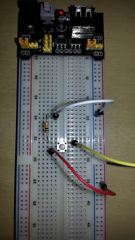
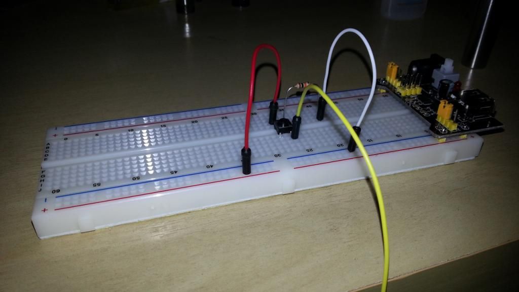
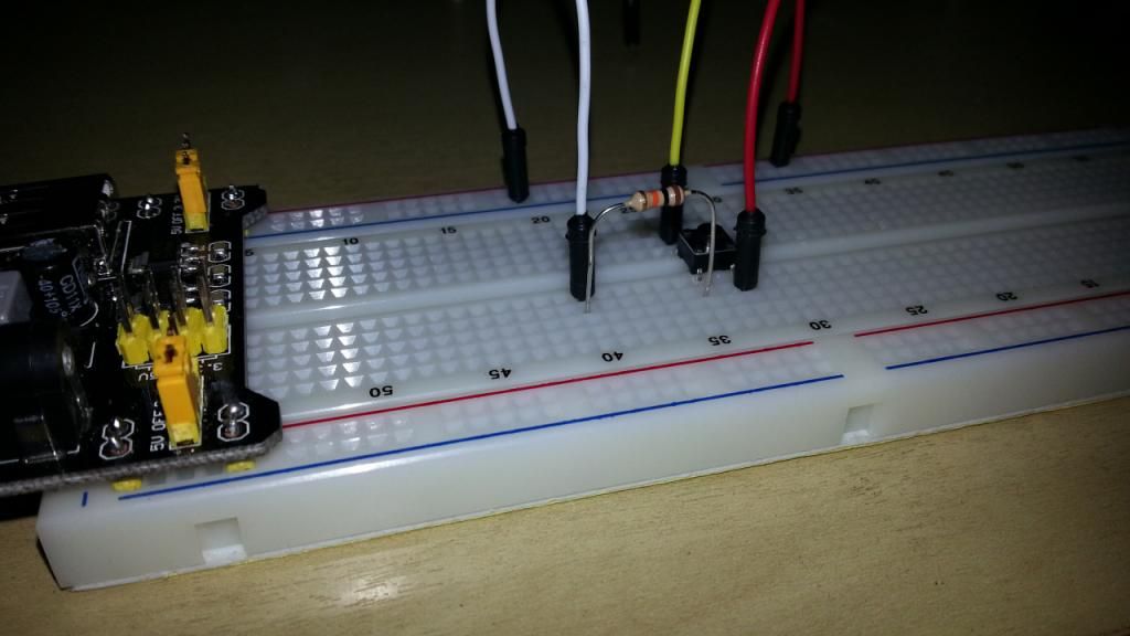
It's also great to see the poster (please excuse lack of name, I'm on tapatalk), using the same hook up I eventually intend to use, utilising the slits above the face plate. Maybe a closer look at your hook up would prove beneficial.

Fantastic work guys. You all deserve much more credit than me. I just got the ball rolling. This thread LITERALLY has everything you need to know, buried within its many pages.

For those of you that send me PMs, please excuse me for not replying individually. Your questions are much better suited in this thread where everyone can see the answers. Dont be scared, even if you ask a stupid question, you're only a screen name, banter is healthy, and certainly not personal. The majority of PMs I'm receiving are all asking similar questions, to which the answers are located here.

Also, a quick check and this thread has now had 51,300 views :) It appears to be one of the most popular currently active threads. Happy days.

The techniques can be used in a vast array of other applications too, with a little imagination. Any chance of a mod making it sticky? :)

Dani

Good to see ya back on here dude, very much looking forward to seeing the first post updated with the final details on getting the system rigged up inside the helmet. Pretty sure we must have enough info here to get the helmet all working now. Good to see a fellow UK person on here too btw.

- - - Updated - - -

hey, I was just wondering if an Arduino Eleven would work for this? thanks.

Looks compatible to me!
 
First post won't be updated with that information for a long while, if ever (depending on other people describing their own hook ups). As mentioned lots of pages back, my helmet will probably never see the motorised mechanism now. I had a very short time limit for that project and all my time is now spent on commissions. Nobody has really detailed their own fixings so the information isn't here yet. Its only the last few days we've started seeing example videos. Plus I personally believe that mounting is entirely down to personal preference and trial and error. I don't think a tutorial for that is required. Unlike electronics and code, which trial and error doesn't work for. That was my mission for this thread. If by some stroke of luck I manage to get mine finished, I will post my method.

The first post needs updating with battery suggestions, mathematics calculation advice, resistor advice, a few more codes, links to other ideas, links to other sources, credits... Etc. Basically all the information located in this thread, tidied up and stacked in one place. It's going to take literally HOURS! :,(
 
Last edited:
The first post needs updating with battery suggestions, mathematics calculation advice, resistor advice, a few more codes, links to other ideas, links to other sources, credits... Etc. All information located in this thread tidied up and stacked in one place. It's going to take literally HOURS! :,(

you can start by editing the resistor you used on the 1st page, it is a 10K ohms (normal value for a pull down resistor), not a 10ohms like you said.

For Battery packs + a Vreg:

Li-Ion Batteries (18350, 18500 18650 @3.7V with 1200~3000mA/h) linking the batteries in series to have @ 7.4V
Li-Po cells (those used for RC cars and heli, they come in a block usually working @ 7.4V with 2000~8000mA/h)
 
Hi guys i changed my servos today and the position of them and how they open the faceplate it opens wider now so ive done a short video to show you and also i try and explain the hinge and the jaw system to try and help those people having trouble so i hope this helps .....enjoy

Ironman Faceplate & Jaw Explanation - YouTube

That looks amazing man, would you be kind enough to show us a close up of how you linked the hinges to the push rods?
 
Hi guys i changed my servos today and the position of them and how they open the faceplate it opens wider now so ive done a short video to show you and also i try and explain the hinge and the jaw system to try and help those people having trouble so i hope this helps .....enjoy

Ironman Faceplate & Jaw Explanation - YouTube

Looks great. I was just "attempting" to create something like this. Getting close but this seems to be just like what I want. Excellent job.
 
That looks amazing man, would you be kind enough to show us a close up of how you linked the hinges to the push rods?


here you go mate hope this helps also ive photoshoped the pics of the templates to show you where ive attached the push rod, the end of the push rod that is attached to the jaw is just bent wit Z pilers and pushed into a hole


omg, thankyou so much! I've been looking for this for so long and finally haha. When I finish building my helmet, I'm going to use your setup (if you don't mid of course).
 
Clean design, i'm using almost the same system, but mine ins inverted, the servos goes down to open the helmet and return to 45º to close it.
 
Ok, I am working on this project now and I am running into a few issues. I hope someone can help. I bought the Arduino Ultimate Microcontroller Pack at Radio Shack and have started working with Arduino. I did a few of the tutorials to just get things working and decided to try out the set up listed in the first post here. I have connected everything and then added the code but here are some problems I am having.

When I plug the board in and upload the code the light blinks once and then servo 2 continuously moves.
Servo 1 does not move at all.
The Light Emitting Diode (LED) is not illuminated.
When I push the button, nothing changes.

Any help would be much appreciated.

Here are a few photos of what is going on.

image-1.jpegimage.jpegphoto.JPG
 
Ok, I am working on this project now and I am running into a few issues. I hope someone can help. I bought the Arduino Ultimate Microcontroller Pack at Radio Shack and have started working with Arduino. I did a few of the tutorials to just get things working and decided to try out the set up listed in the first post here. I have connected everything and then added the code but here are some problems I am having.

When I plug the board in and upload the code the light blinks once and then servo 2 continuously moves.
Servo 1 does not move at all.
The Light Emitting Diode (LED) is not illuminated.
When I push the button, nothing changes.

Any help would be much appreciated.

Here are a few photos of what is going on.

View attachment 198530View attachment 198531View attachment 198532
im no expert but looks to me like you have the control cable missing from your button should be one going from the switch to the adruino pin 2 and led should be pin 5 not 2
 
When I plug the board in and upload the code the light blinks once and then servo 2 continuously moves.
Servo 1 does not move at all.
The Light Emitting Diode (LED) is not illuminated.
When I push the button, nothing changes.

Any help would be much appreciated.

Here are a few photos of what is going on.

OK, your push button is shorted, 5V is passing directly to the GND, also there is nothing going to the arduino from the push button, if you don't feed any input nothing is going to happen, and finally your led is linked to the wrong pin on the arduino, the right pin is the pin 5 for the led, and the pin 2 for the push button.

So, lets make a few changes, follow those instructions and try it out:

Put the push button on the pins: 26E, 26F and 28E and 28F
put the +5V on the pin 28D
put a resistor from the pin 26D to 20D
put a wire from 20E to the negative stripe
and finally put a wire from the pin 2 on the arduino to the pin 26G

*also, change the led to the pin 5 of the arduino!

now this thing have to work like a charm!

Some reference pictures in the spoiler:
20130529_005534_zps89fb0688.jpg

20130529_005624_zpscbda2f75.jpg

20130529_005610_zpsb0590022.jpg

Use that setup you have going just as a test platform, to get it working for real you will need a regulated 7.4V to 5V battery pack to feed the servos, cause the arduino alone cant do it.

I hope that help you out.
 
im no expert but looks to me like you have the control cable missing from your button should be one going from the switch to the adruino pin 2 and led should be pin 5 not 2

Thank you, I actually took the picture when I was trying to figure out what was going wrong. I changed that back but had the same result.
 
OK, your push button is shorted, 5V is passing directly to the GND, also there is nothing going to the arduino from the push button, if you don't feed any input nothing is going to happen, and finally your led is linked to the wrong pin on the arduino, the right pin is the pin 5 for the led, and the pin 2 for the push button.

So, lets make a few changes, follow those instructions and try it out:

Put the push button on the pins: 26E, 26F and 28E and 28F
put the +5V on the pin 28D
put a resistor from the pin 26D to 20D
put a wire from 20E to the negative stripe
and finally put a wire from the pin 2 on the arduino to the pin 26G

*also, change the led to the pin 5 of the arduino!

now this thing have to work like a charm!

Some reference pictures in the spoiler:

Use that setup you have going just as a test platform, to get it working for real you will need a regulated 7.4V to 5V battery pack to feed the servos, cause the arduino alone cant do it.

I hope that help you out.


Thank you very much. I changed the set up to what you suggested (pictures below) and get the same result except now the led stays on.

image4.jpegphoto.JPG
 
Back
Top