Iron man motorised faceplate electronics tutorial!!!

I will use external components, just to be sure, i already inverted the logic on the code, but i'm going to keep using the physical pull down anyways, i already sent the files to Itead

10 eye board, and 10 regulator boards with pins to the servos and wiring
 
awesome.!

post when you get them (in 3 weeks) ;)

still should be another fun step in this project for ya! :)
 
It will take more than 3 weeks, believe me bro, lol, the customs of my country are nasty! I'm expecting to receive it in 8 to 10 weeks, thats the usual time things from china takes to arrive here.
 
the numbers besides "myservo1.write" are the servo signal

but i don't know what code you are using, so i can't help further.
 
Iam useing 7 sinzz one
Iam new to all this so I have a few questions, i want
To edit 7sinzz code if I want servo one to move up
Instead of down how is that done? And if I want
It to move less how is that done? And if I want it to go faster or
Slower how's that done? Sorry for all the questions
Thanks, Colin.
 
Like i said, depends on what code you are using, the code without the fade effect you can change the speed of the servos by adjusting the step angles of the servos on the code

Code:
for(pos = 0; pos <= 180; pos += 10) // goes from 0 degrees to 180 degrees in steps of 10º  <-- This is the speed
{ 
myservo.write(pos); // tell servo to go to position 'pos'
}
for(pos1 = 180; pos1 >= 0; pos1 -= 10) // goes from 180 degrees to 0 degrees in steps of 10º <-- This is your speed
{
myservo1.write(pos1); // tell servo to go to position 'pos1'


to make it move up or down, less or more, i already gave you the answer on the last post, POS and POS1 are the variables that adjust your servo final position. (varies from 0º to 180º)

------------------------------------------------------------------------

To make it possible on the code with the fade effect you have to implement pos and pos1 variables on the code, and ajust the code to work with it, since this code in particular works with straight position.
 
Last edited:
Hey guys really need some help. Thanks to this thread ive decided to give it a go at making an iron man suit however, i have followed all the advise i can see on here but can not seem to get my servos to work? Im using the bluebird BMS-810DMG servos for the faceplate. Im using the code found on the first post. the one with flickering eyes. I have changed a couple of things on my board as i believe these servos require an additional power source? really i am no good at this stuff and was wondering if anyone could cast an eye over what i have done and let me know if you can see anything i may have done wrong? photo 2.JPG
many thanks in advance guys
 
Tony Hughes

The push button is in the wrong place, place it in the middle of the protoboard like in this picture:
20130529_005534_zps89fb0688.jpg

and it will work.

why? Cause the way it is now makes the push button to be irrelevant to the circuit itself, physically it is there, but the circuit do not see it, once the legs of the push button are circuit shortened (the button is open but the protoboard is making it closed anyways), placing it in the middle of the protoboard avoids that


Spirit of ob1

you need a FTDI (TTL) cable or adapter.
 
Last edited by a moderator:
Tony Hughes

The push button is in the wrong place, place it in the middle of the protoboard like in this picture:

and it will work.

why? Cause the way it is now makes the push button to be irrelevant to the circuit itself, physically it is there, but the circuit do not see it, once the legs of the push button are circuit shortened (the button is open but the protoboard is making it closed anyways), placing it in the middle of the protoboard avoids that


Spirit of ob1

you need a FTDI (TTL) cable or adapter.


Ok have just tried that set up but the servos still don't respond? The LEDs work fine as they should but absolutely nothing from the servos :/ will it have anything to do with what servo I'm using?
 
Im not sure what type of 'cable' that is.. a link on it?

I 'have' used cell phone data cables....

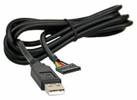
the problem with this is.. some/most do NOT have the RESET/DTR pin broken out for auto-reset..

which means you'll have to manually push the reset button (timing the bootloader process0 to be able to upload sketches/code to your board..

IF your board has a USB port.. you will NOT need the FTDI cable..

I had posted to the FTDI cable "I" use and recommend.. :)


and.. (again).. as stated MANY MANY MANY times before in this thread.. DO NOT USE 9v (rectangle) batteries!.. they are complete JUNK!..

IMHO.. you are not getting enough current to your servo's.. do like everyone else has said..

1.) use a 'real' battery pack/source.. either a bench top power supply. or a +7.4v li-ion pack or something..
2.) it 'looks' like you may be doing this.. but ensure you have the GNDs connected..

I 'think' you have the GND rail from right side of the breadboard.. going to the LED row.. then to the GND rail on the left side of the breadboard?

hard to tell with the blue wires..


3.) I dont see ANY resistor on that led (you must hate the little guy?) ;)


IMHO.. set up the breadboard FIRST...

meaning..

attach battery pack (not that one, but a real one).. the same way you have it now..

then take the TWO power rails from the RIGHT side (where the battery pack is connected to)..

and connect those outside rails to the outside power rails on the LEFT side of the board..

now you have a 'powered' proto-board.. that you can add components, and tap the rails for the power..

I would then take a wire from the GND rail on the breadboard and connect it to the Arduino GND pin..


!!!!

Well from the pic,.. your servo's might be dead..
you are NOT regulating the voltage from the 9v battery pack.. you have connected the servo's directly to it..

most servo's can ONLY take +4.8v - +6v (maybes yours are different?)


some rules of thumb.

ALWAYS use a resistor with LEDS (always!.....yes, always) :)

read up on the parts/components you plan on working with, under their limitations and requirements.... (ie: operating voltage/current..etc) (get familiar with their datasheets.. yes, they suck and are cryptic.. but eventually they will get easier to read and yield good information)

it LOOSK liek you have the +3.3v pin on the Arduino conected to the left side power rail on the breadboard?.. why? (dont do that) :)

the only thing on the breadboard that should be connected to the Arduino is:

1.) the GND rail (not POS rail)
2.) 1 wire to the button
3.) 1 wire to servo 1 (not really the breadboard but still)
4.) 1 wire to servo 2 (not really the breadboard but still)
5.) 1 wire to the LED

thats 5 wires.. (I count 6 on yours) :)

again this is from a pic.. and I could be wrong.. so explain if I have something in-correct on my interpretation
 
Back
Top