You are using an out of date browser. It may not display this or other websites correctly.
You should upgrade or use an alternative browser.
You should upgrade or use an alternative browser.
Iron man motorised faceplate electronics tutorial!!!
- Thread starter 7sinzz
- Start date
Demolition
Well-Known Member
Hi guys i first want to say a massive thankyou to 7sinnz and xl97 without you guys i would be lost i have no idea what im doing but ive got it working at least heres my setup... Iron man helmet electronics - YouTube
what i would like is the button to be wireless but i have no idea what else i need or even how to write the code any help would be greatly accepted
oh the code i used was 7sinzz code on the first page
what i would like is the button to be wireless but i have no idea what else i need or even how to write the code any help would be greatly accepted
oh the code i used was 7sinzz code on the first page
what i would like is the button to be wireless but i have no idea what else i need or even how to write the code any help would be greatly accepted
The wireless you refer for is like remote controlled with a radio frequency or remote controlled by wireless commands?
if you wanna it to be controlled by RF you can buy a RF module with a remote control working on the same frequency and do the same thing i'm doing on my project, and you don't even need to change the code!
the video is in my native language but you can turn on the captions to watch it with English subtitles.
Last edited by a moderator:
xl97
Master Member
Demolition -
thanks!..
I have awesome & talented people I learn from at the Arduino based forums and blogs and another prop maker/EE (guru) at another forum, who, IMHO (personally) set the standards on electronics for props in many areas. I use Arduino and pre-made lincoln-logs to build my stuff...lol.. people like him/others 'make' those lincoln logs I play with! LOL
and your set-up looks good!..
dont worry is you dont understand all this stuff..... that wasnt your focus.... just a step toward your end goal.. for people like me and 'memebr'... we kind like this stuff.. and I can tend to make this aspect/step longer (more complicated) than needs to be sometimes, because I like it and find it fun and enojy learning about it along the way..
(Im the opposite with machining however.I know many machinists who are always tweaking or modd'ing the lathe/mill ITSELF.....which is awesome..... but for me, I see it as more of a 'tool' i just want it to 'work' so I can closer to my end goal/project...etc)")
every has their interests.
my only suggestion would be to NOT use those 9v batteries..
also what leds are you using? (are those pre-wired ones? what are they rated for? resistors in there?)
memebr - still dig'in the remote addition!
thanks!..
I have awesome & talented people I learn from at the Arduino based forums and blogs and another prop maker/EE (guru) at another forum, who, IMHO (personally) set the standards on electronics for props in many areas. I use Arduino and pre-made lincoln-logs to build my stuff...lol.. people like him/others 'make' those lincoln logs I play with! LOL
and your set-up looks good!..
dont worry is you dont understand all this stuff..... that wasnt your focus.... just a step toward your end goal.. for people like me and 'memebr'... we kind like this stuff.. and I can tend to make this aspect/step longer (more complicated) than needs to be sometimes, because I like it and find it fun and enojy learning about it along the way..
(Im the opposite with machining however.I know many machinists who are always tweaking or modd'ing the lathe/mill ITSELF.....which is awesome..... but for me, I see it as more of a 'tool' i just want it to 'work' so I can closer to my end goal/project...etc)
every has their interests.
my only suggestion would be to NOT use those 9v batteries..
also what leds are you using? (are those pre-wired ones? what are they rated for? resistors in there?)
memebr - still dig'in the remote addition!
Last edited by a moderator:
xl97
The remote addition you wanna implement is a lil bit more fancy than the one i'm using now
But i wanna do something similar to what you wanna, i'm still looking for what hardware to buy, I'm thinking on grab a serial BT adp compatible with arduino that JY-MCU makes ($6,00~8,00)
I also need to study more in a field that i don't have much knowledge, cause i wanna make an Android APP with a cool layout to use with it
Last edited by a moderator:
The BT control i will implement just on my complete faceplate that will be resting in a Display base inside a acrilic box. (my 1st helmet came out a lil bit wrong, so i will use just the faceplate!)
and i don't wanna use a RF remote control to trigger it cause i lose those things all the time, so the cellphone will be a perfect remote controller for that, it is aways in my pocket or in front of me.
and i don't wanna use a RF remote control to trigger it cause i lose those things all the time, so the cellphone will be a perfect remote controller for that, it is aways in my pocket or in front of me.
JayCVenlo
Sr Member
Okay so i need an external power source? I allready tried running the arduino board with a 9v Battery. just for testing. Same problem. But the output power will stay the same of course. The Arduino generate 5Volts output, right? My servos only need 4,6V minimum, so why is it a problem?
But what i dont want is 3 different power sources:
1. for the ardiuno nano 1. for the servos 1. for the LED strip with build in resistors.
What would you folks recommend for a setup?
(Maybe if someone would like to help me send me an PM, so we can communicate easyer. Maybe via FB.)
many thanks.
But what i dont want is 3 different power sources:
1. for the ardiuno nano 1. for the servos 1. for the LED strip with build in resistors.
What would you folks recommend for a setup?
(Maybe if someone would like to help me send me an PM, so we can communicate easyer. Maybe via FB.)
many thanks.
Okay so i need an external power source? I allready tried running the arduino board with a 9v Battery. just for testing. Same problem. But the output power will stay the same of course. The Arduino generate 5Volts output, right? My servos only need 4,6V minimum, so why is it a problem?
But what i dont want is 3 different power sources:
1. for the ardiuno nano 1. for the servos 1. for the LED strip with build in resistors.
What would you folks recommend for a setup?
(Maybe if someone would like to help me send me an PM, so we can communicate easyer. Maybe via FB.)
many thanks.
The Arduino board have a max 40mA (0.04A) current output and a servo uses more than that with load a servo can reach 3A (3000mA), your servos are starved.
you don't need 3 different power sources, you just need one, use a Vreg to to step down the voltage to the other things on the circuit, keep all the GND together, the Arduino should just be used as a digital trigger to command stuff, not to power things.
xl97
Master Member
DONT USE 9V (RECTANGLE) BATTERIES!..
they are notoriously CRAP!!!!
And yes.. the Arduino has a +5 RAIL.... but can only supply (max/maybe) 40mA of current of any given pin... your servo will need more than that, especially under load..
and when we say external power source, you can still use one battery pack to power everything.. but you connect it directly to the battery pack.. not through the Arduino..
Battery Pack A >>> Arduino
Battery Pack A >>> servo(s)
Battery Pack A >>> led strip
NOT...
Battery Pack A >>> Arduino >> Servo >> leds
keep in mind.. EACH of these require specific and different voltages (so regulate appropriately)
I dont do "FB"...
and any help should be posted here for everyone to benefit from... (although all your answers are here already, posted several times)
edit-
I see memebr beat me to it! lol..
Last edited:
edit-
I see memebr beat me to it! lol..
2 brains thinks better than just 1 :lol
---------------------------------------------------
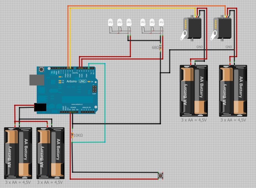
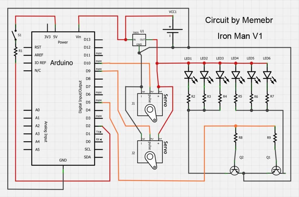
And for anyone that wanna use my circuit, here it is:
Last edited:
Spirit of ob1
Master Member
I feel like an idiot!, id like to use your layout member, but i dont even understand it.. :confused
is the one Drack posted a good one? that one i understand
:confusedis the one Drack posted a good one? that one i understand
Last edited:
Spirit of ob1
Master Member
Thanks!!! D
DSpirit of ob1
Master Member
Its not mine remember. I dont want to get in trouble with who made it
changed it

Similar threads
- Replies
- 1
- Views
- 307
- Replies
- 1
- Views
- 449
- Replies
- 2
- Views
- 539