You are using an out of date browser. It may not display this or other websites correctly.
You should upgrade or use an alternative browser.
You should upgrade or use an alternative browser.
Iron man motorised faceplate electronics tutorial!!!
- Thread starter 7sinzz
- Start date
S
Shinon
Guest
I don't understand  too many people post their code i don't know which one is the good one
Envoyé depuis mon GT-I8190 avec Tapatalk
too many people post their code i don't know which one is the good oneEnvoyé depuis mon GT-I8190 avec Tapatalk
Djstorm100
Active Member
What's the point of the 2nd board? Why not hook everything up to servo board?
Djstorm100
Active Member
what second board? what set-p are you talking about? links? pics? quotes? anything?
most people are using an Arduino (1 board)..
First post shows servo board, white board with green led sticking out of it and random wires
For this you will need:
Arduino UNO + USB cable (available on ebay or many electronics suppliers)
Arduino software (available here)
2 servo motors
1 LED
1 push button
1 10ohm resistor
1 breadboard
13 breadboard cables
The resistor you are using is a 10K ohms (10.000 ohms) resistor. it is not a 10ohms resistor.
i tried to assemble the same electronic built as you did, and my servos goes from 0 to 180 and just start to make crazy noises, the led comes on and the push button does nothing.
I'm trying to fix it, since the same code works for you.
any tips?
xl97
Master Member
1.) a servo will NOT do more than '180' degrees... (unless mod'd or bought pre-mod'd)
2.) you'l be LUCKY if you really get 180 degree of movement
trim it back and see if the same 'noise' happens.
also.. tie/connect all GND lines..
there is a battery pack powering the servo.. and something powering the Arduino as well.. connect both GND lines see if that helps)
2.) you'l be LUCKY if you really get 180 degree of movement
trim it back and see if the same 'noise' happens.
also.. tie/connect all GND lines..
there is a battery pack powering the servo.. and something powering the Arduino as well.. connect both GND lines see if that helps)
1.) a servo will NOT do more than '180' degrees... (unless mod'd or bought pre-mod'd)
2.) you'l be LUCKY if you really get 180 degree of movement
Thanks for the help dude!
But after 1 liter (32 fl oz) of coffee i figured out what was wrong, the dude that made both of the codes on the 1st page did not specify if the push button need to be normally open or normally close, i was using a normally open push button, but this project needs a normally close push button (the button need to let pass +-5V when not pressed and let pass 0V when pressed).
I made it work just changing the push button i was using.
I need to invert the logic on the coding to make it work with the push button i want, also it will reduce a lot of battery consumption, cause like this code is, the board is constantly drawing on the 5V, inverting the logic it will just draw power when needed.
some pictures of the circuit working:
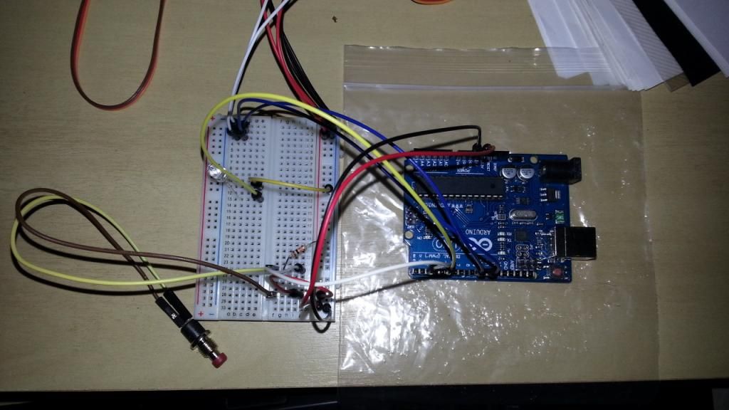
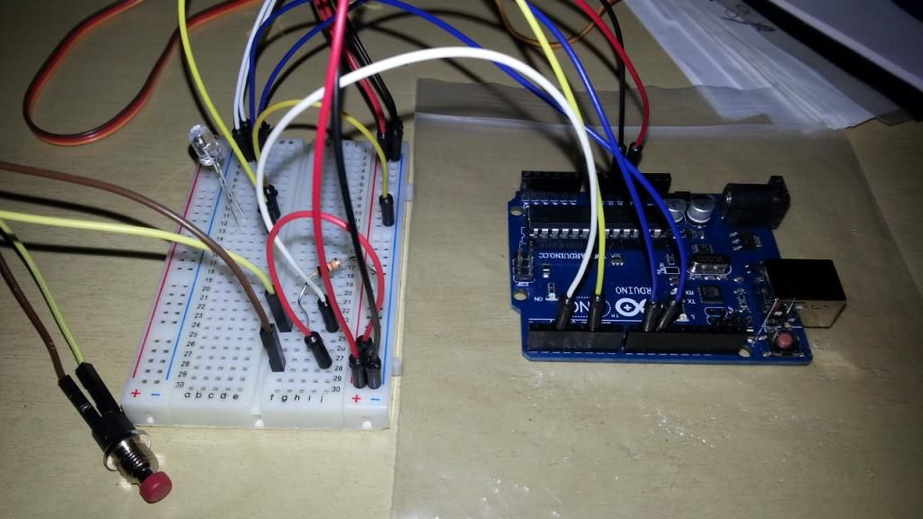
push button order:
-Positive rail to J28
-Port 2 on arduino to J24
-10K ohms from H24 to negative rail (pull down)
-One side of the push button on F24, the other one on F28
bingo, its working.
Djstorm100
Active Member
Thanks for the help dude!
But after 1 liter (32 fl oz) of coffee i figured out what was wrong, the dude that made both of the codes on the 1st page did not specify if the push button need to be normally open or normally close, i was using a normally open push button, but this project needs a normally close push button (the button need to let pass +-5V when not pressed and let pass 0V when pressed).
I made it work just changing the push button i was using.
I need to invert the logic on the coding to make it work with the push button i want, also it will reduce a lot of battery consumption, cause like this code is, the board is constantly drawing on the 5V, inverting the logic it will just draw power when needed.
some pictures of the circuit working:
http://i3.photobucket.com/albums/y87/oozi/20130526_061140_zpsbc994e33.jpg
http://i3.photobucket.com/albums/y87/oozi/20130526_061147_zpsc70709ee.jpg
push button order:
-Positive rail to J28
-Port 2 on arduino to J24
-10K ohms from H24 to negative rail (pull down)
-One side of the push button on F24, the other one on F28
bingo, its working.
What do you mean by inverting?
What do you mean by inverting?
Inverting the logic, where you have 1, you put 0, where you have 0, you put 1 ...
also works for HIGH and LOW (its the same thing of 0 and 1)
But to do that you have to tweak the code a lil bit
xl97
Master Member
In Arduino...
you can/should NOT have a pin 'floating'..
meaning the pin itself needs to be tied to either V++ or GND...
this can be done by using a resistor to connect to GND rail.. -or-.. you can use an internal PULL-UP resistor.. which bring it HIGH/V++
you 'can' still use a normally open switch.. when pressed closed/completes the circuit....
you can still use the same normally OPEN switch.. and when connected/closed completes the circuit to either GND or V+
in my code.. I usually use internal PULL RESISTORS, (because it built-in and doesnt use an external component)..
depending on what you do..
you either check for the pin to be high (V++) or low (GND)...
but as you see.. it only be HIGH or LOW when the switch is closed/complete..
this can be done by using a resistor to connect to GND rail.. -or-.. you can use an internal PULL-UP resistor.. which bring it HIGH/V++
Bro, I activated the pull up resistor in the arduino pin i was using to the button, servos started to behave crazy, deactivated, same thing, activated the pull up back and included the pull down at the same time, crazy servos, deactivated the pull up ans kept the pull down resistor the servos started to behave normally.
the thing is working great now.
thats makes no sense..
Believe me, i was thinking the same thing during the process! he he
Djstorm100
Active Member
Inverting the logic, where you have 1, you put 0, where you have 0, you put 1 ...
also works for HIGH and LOW (its the same thing of 0 and 1)
But to do that you have to tweak the code a lil bit
I'm new to programing... and trying to learn. Could you explain a little more in to depth? Thanks
Hello everybody !
I have followed the tutorial (but only with 1 servo) and it's working So THX YOU !!!
But I have one question : My servo sounds to make a sort of noise like if it is always working.
There is a way in the arduino to send to servo "stop" when it is at 0 or 180 ?
Thanks in advance and excuse my english !
I have followed the tutorial (but only with 1 servo) and it's working
So THX YOU !!!But I have one question : My servo sounds to make a sort of noise like if it is always working.
There is a way in the arduino to send to servo "stop" when it is at 0 or 180 ?
Thanks in advance and excuse my english !
Are you using this transistor as just a trigger?
interesting concept, i was thinking in use those stripes with 4 or 5 smd leds per secion, i may use a transistor, and put the arduino to trigger it and fire up the leds powered by the battery pack.
Similar threads
- Replies
- 1
- Views
- 311
- Replies
- 1
- Views
- 456
- Replies
- 2
- Views
- 545