Help- Back the Future Doc's Amplifier

Tenaciousbt

Well-Known Member
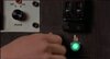
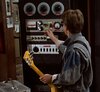
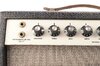
Hello all. I'm attempting to replicate the control panel on Doc's Amplifier. I've identified several of the components. Some are easy to find but pricey. Others are difficult to find. I was hoping, some of you would be willing to help me with my search. I'm sharing pics and descriptions of what I know and am looking for.

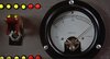
This first one is made by general electric. Type 157. Very hard to find.
AF1QipO_V0pYh7zKieZIbt4pE7AjMWvLL054GNilaoiP


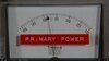
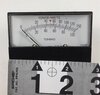
This one is made by Simpson. It's segmental because it goes form 100-130. I've seen these but I was too late to buy it.
AF1QipOh49zZhulQ8oKigxcemKw4Fk3SuWGy1QPf1HCM


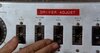
This last one. I'm looking at the bottom panel. It has a bunch of individual circuit breakers on it. Any ideas?
AF1QipOL_ccdVq6XyTyAJ6o4aMPcdxbfiZJsYkgH2cRi
 

Attachments

  • 1.jpg
    1.jpg
    1.1 MB · Views: 1,644
  • control panel 2.jpg
    control panel 2.jpg
    798.7 KB · Views: 4,683
  • controls meter guage.jpg
    controls meter guage.jpg
    1.2 MB · Views: 1,540
  • Simpson segmental voltmenter guage.jpg
    Simpson segmental voltmenter guage.jpg
    212.3 KB · Views: 1,104
  • single breaker switches.jpg
    single breaker switches.jpg
    1.2 MB · Views: 1,395
  • Vintage 1960'S Gibson GA-5T Skylark 5 Вт 1x10.jpg
    Vintage 1960'S Gibson GA-5T Skylark 5 Вт 1x10.jpg
    328.9 KB · Views: 1,064
  • s-l500.jpg
    s-l500.jpg
    31.6 KB · Views: 976
Looks somewhat similar to the breaker panels on my old weather radar. Looks like it has "Klystron" or something similar printed above one of the breakers (my old radar used a Klystron before we upgraded to one with a magnetron). Definitely from some sort of tube-based transmitter like a radar, microwave TX or even some sort of low-power UHF.
 
Bump, come on guys I need some more help. Especially with this power supply/amplifier, or whatever it is with these breaker switches. It says things like, "autotransformer" "PA Plate" "Klystron HV" "LV Plate" "LV filiment" "HV filiment". It says that above the breaker switches and has a Variac dial on it too. Any ideas?
 
I believe there was someone on a FB BTTF group page that did a 1:1 scale build of the amp.

They may be a member here too, just have to do some digging.
 
From my understanding, the "Driver Adjust" panel aren't breakers, just switches. Similar to wall light switches, but different form factor. I could be wrong, obviously.

McFlyDallas
 
Hello all, new here. I’m also trying to identify some of the parts used to create the Doc Brown amp - specifically, I’m trying to identify the three, large, top dial plates. Would anyone be so kind as to assist? Many thanks!!
 
How is this project turning out? Im a guitarist are you making this amp functional? That would be epic ,and i know some people on reverb.com would probabaly the runners would put it up on there front page to Help sell a beauty like that not only collectors but if it made any kind of noise it would or just. A prop you would be able to sell it for just about anything im sure id love to see any of your progress ,
thanks
 
I'm working on this project myself, Tenaciousbt and have ID'ed some of the components (wish I knew about this thread earlier!). The switches are all Heinemann vintage circuit breakers; they're all pictured below. In the film, after the keyed switch is turned on, the first switch thrown is a DPDT Heinemann breaker; the second, larger one is a 230V AC triple pole, single-throw breaker; and the six thrown in sequence are all 15-amp SPST Heinemann breakers (the "Re-cirk-it" type, I think, with the two white status arrows pointing to On or Off). If you play the scene at very slow speed, the Heinemann logo on the plate is even visible. It looks like the second one in from the right in the film is a slightly different type, without the arrows, but I managed to get 6 of this same type at once.

As has been mentioned, too, the dials/knobs are all from variable auto-transformers. The first large knob on the bottom left of the lower-most control panel is a Type 200B VARIAC autotransformer by General Radio (in the black box in the photo below); the three across the top are Type 21 Powerstat transformers by Superior Electric, model EN116b (in the grey box in the photo below). None of the S.E. Powerstats have their correct knobs, though; they all seem to have large generic bakelite ham radio knobs.

IMG_3176.JPG
 
I'm working on this project myself, Tenaciousbt and have ID'ed some of the components (wish I knew about this thread earlier!). The switches are all Heinemann vintage circuit breakers; they're all pictured below. In the film, after the keyed switch is turned on, the first switch thrown is a DPDT Heinemann breaker; the second, larger one is a 230V AC triple pole, single-throw breaker; and the six thrown in sequence are all 15-amp SPST Heinemann breakers (the "Re-cirk-it" type, I think, with the two white status arrows pointing to On or Off). If you play the scene at very slow speed, the Heinemann logo on the plate is even visible. It looks like the second one in from the right in the film is a slightly different type, without the arrows, but I managed to get 6 of this same type at once.

As has been mentioned, too, the dials/knobs are all from variable auto-transformers. The first large knob on the bottom left of the lower-most control panel is a Type 200B VARIAC autotransformer by General Radio (in the black box in the photo below); the three across the top are Type 21 Powerstat transformers by Superior Electric, model EN116b (in the grey box in the photo below). None of the S.E. Powerstats have their correct knobs, though; they all seem to have large generic bakelite ham radio knobs.

View attachment 1431041
This is great! I would love to stay in touch with you on this and what you find. I am not an electrician or an engineer. I will need help once I get everything.
 
I'm working on this project myself, Tenaciousbt and have ID'ed some of the components (wish I knew about this thread earlier!). The switches are all Heinemann vintage circuit breakers; they're all pictured below. In the film, after the keyed switch is turned on, the first switch thrown is a DPDT Heinemann breaker; the second, larger one is a 230V AC triple pole, single-throw breaker; and the six thrown in sequence are all 15-amp SPST Heinemann breakers (the "Re-cirk-it" type, I think, with the two white status arrows pointing to On or Off). If you play the scene at very slow speed, the Heinemann logo on the plate is even visible. It looks like the second one in from the right in the film is a slightly different type, without the arrows, but I managed to get 6 of this same type at once.

As has been mentioned, too, the dials/knobs are all from variable auto-transformers. The first large knob on the bottom left of the lower-most control panel is a Type 200B VARIAC autotransformer by General Radio (in the black box in the photo below); the three across the top are Type 21 Powerstat transformers by Superior Electric, model EN116b (in the grey box in the photo below). None of the S.E. Powerstats have their correct knobs, though; they all seem to have large generic bakelite ham radio knobs.

View attachment 1431041
Did you ever figure out what panel the 15amp Heinemann breakers were put in? Or do you think that was a custom build for the movie? Everything else was pulled from other things.
 
Did you ever figure out what panel the 15amp Heinemann breakers were put in? Or do you think that was a custom build for the movie? Everything else was pulled from other things.
It does look like a transmitter / antenna control panel, but definitely seems to be homemade: the lettering has misspellings, and some of the baselines are off, like in the label Variable Autotransformer, where the "variable" is slightly higher, etc. Possibly a Letraset or dry transfer application? Maybe it was just a homemade panel found at something like Apex Surplus. Until I can get a custom panel engraved, for the time being I'm just going to use a black-on-clear label maker and a sans serif font to replicate it on some aluminum. I'm going to try to get the cabinet and panels built this month (after the last of my components come in); will post photos!
 

Your message may be considered spam for the following reasons:

If you wish to reply despite these issues, check the box below before replying.
Be aware that malicious compliance may result in more severe penalties.
Back
Top