Functional Pip-boy 3000 Mk IV from Fallout 4

SLS 3D printed Nylon is solid, although all Nylon does absorb moisture, but the material is effectively as waterproof as any other plastic.

However, making something like the Pip-Boy water proof is a VERY tall order. Some of the knobs can be sealed with O-Rings, but that also makes them prone to binding up. But the scroll wheel knob couldn't be waterproofed and still turn a gear. The LCD screen can be made water-resistant to light rain with a simple adhesive gasket, but it can't be made waterproof due to the waterpressure against the large surface area of the screen. The tactic button uses don't have enough force to overcome a gasket, and you won't find small waterproof or even resistant buttons. The speaker vent would have to be covered with plastic and wouldn't work well. Finally there is the matter of the gaping hole where you arm goes through, the simplest way here would be to try to seal the the person's arm, but again there is the bottom latch seam which would be difficult to seal up.

------------------------------

Project update, no images:

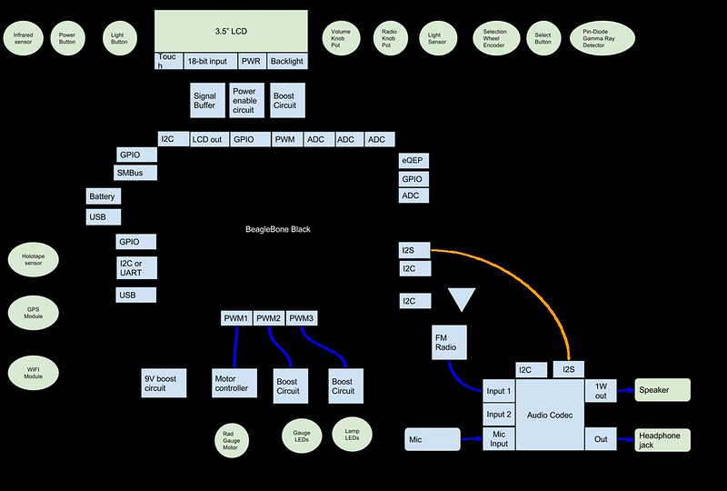
Currently I am working on the tedious task that is researching, and selecting electrical components. I am starting with the most difficult part, which is the LCD. The circuit which can drive one LCD screen doesn't necessarily work on another. Different screens have different ways to get the data to the screen. Then there is the task of voltage boost converters which take the 3.7V from a lithium polymer battery and boost it to the 19.2V that the screen backlight requires. Add to that modeling connectors and creating schematic symbols and you have a lot of time just preparing to design the schematic.

I have started using KiCAD to do the schematic and PCB. It seems this year they have fixed a lot of the grips that kept people from recommending it in the past. Why am I not using Eagle? Because my main board is bigger then microscopic 100mm limit that Eagle Free allows. I also will most likely need four layers for the PCB. I considered using Design Spark as it is also free, however I got stuck for hours just trying to make the most basic part footprints. Apparently, in DesignSpark you can draw a line, but you can't edit it easily. If the most basic task was impossible I wasn't going to try the harder stuff in it.

The next hardest task will be the gauge motor, it requires a stepper motor controller and its own voltage boost to work well. Stepper's are not something I have worked with in the past. So I am researching and learning as I go.

This is unfortunately the slow part of the project without any pretty renderings to show you all. I am expanding the bill-of-material estimate as I add major electronics parts. It is nearing $1000, but when I build my prototypes it will cost me at least $1500 to build the first one. $200 of that alone is left over costs in minimum order quantities.

With that said, I have added a Paypal donate button to my website if anyone is interested in helping fund the prototype build.
 
First off, this is incredible, and you're doing a great job.

Re waterproofing, have you thought about something like liquipel? That way you won't have to worry about water getting inside, as all the insides would be hydrophobic. There are companies that you can send devices off to and they will treat them for you
 
You mentioned gearing down a pager motor. They make those already, just so you know. Pololu has two options, actually: 26:1 and 136:1. You would need an encoder or potentiometer of some sort to determine the position.

I'd suggest you aim for an LED backlit LCD vs a CCFL backlit LCD. CCFL backlights are terribly inefficient.

As for waterproofing, you could simple seal the boards themselves with epoxy and worry about individual component waterproofing case by case.
 
@DanielWGK, Those are indeed small geared down motors. I didn't find any that small in my search. However I think the gauge motor I selected will work well. It is designed exactly for driving a gauge needle and holding its position.

The LCD I selected is LED. The 19.2V required for the backlight is because most LED backlights use a series of LED strings. In this case the backlight is two strings of six LEDs wired in series. At 3.2V per LED that works out to 19.2V per string. (3.2x6) The boost circuits for these LEDs are effectively already written out in reference designs. I will use a similar boost circuit to drive the lamp and gauge backlight LEDs (which also will be a series of LED strings)

The liquipel stuff is expensive as far as I have seen, $90 for a tablet. The NeverWet stuff is also expensive and leaves a hazy coating on everything. If someone wants to seal their kit after they get it that is up to them.
 
Last edited:
@zipwizared

I would like to start off by saying that I have done quite some research on you and I am a fan of your work. I too was upset when I found out that the pip-boy was just a phone holder. when I first saw the pip-boy I thought that maybe there was a device that plugged into the phone so then the knobs would react to the phone. I dreamed of doing this my self but I have no experience with this kind of project. When I was researching your work, I began to get very excited that your a fallout fan and are doing the pip-boy very good justice.

That all being said I am behind you 100%. If the pip boy was to ever become a thing you would be the man to do it. I know that people have made pip boys b4 but they usually have a Raspberry Pi or they can't put their arm through it. With your permission i would like to share your project with those on Reddit and on Twitter. I feel others would get behind you on this project.
 
Last edited:
This is starting to look so good I'm beginning to think you should alter the appearance in some way so Bethesda doesn't step in claim it somehow.

Sent from my C811 4G using Tapatalk
 
@Btechnician,

Thanks for the compliments. Go ahead and share away, it was posted to both r/Fallout and r/F04 early in the project, but a bump doesn't hurt. I have seen the Raspberry Pi models and while they at least have a screen, they require a lot of external parts to work. My friend's Pip-Boy 3000 which is sitting on my desk right now was fully self-contained. He ripped apart a old windows phone and crammed the guts inside. He at least re-routed the USB and audio, as well as switches. It barely works now as the battery connection is loose. I sort of want something that feels like it was made by Vault-Tec themselves.

@jellis359, There is a danger of course with any project like this that Bethesda can step in and ask me to stop making this. I hope instead they will find super cool and decide to support the project directly. (You hear me Bethesda, I love you!) After all they had their chance to make a real Pip-Boy. While I still think the Pip-Boy edition is one of the coolest, and frankly low-cost collectible editions of a game, they could have done better. Or at least got the color of the LEDs to match the game.

I am building my own unit no matter what. They can try ripping it off my arm when I am done. As for any possible kits, I have stated that I am not out to make any profit on this project, the kits will mean each creation will be unique. With the cost and skill level required for the kit I don't expect many genuine takers.

------------------------------

Project update:

Work is progressing on the electronics. I finally clobbered enough data from about a dozen different BeagleBone to LCD screen schematics to piece together what I think will work for my LCD. (Each brand/model of LCD is a bit different). I am also planning out the rest of the schematic as a block diagram, I will post the block diagram here once complete.
 
@zipwizard

With your friends permission could you post a pic of his pip boy. But if that is bad thread etiquette then its ok.

Also ceep up the great work balancing something like this between work and home must be a challenge.and lastly I tried to go check out your donations page by pressing the button but nothing happened for me. I'm on a cellphone doing all of this so I don't know if that's a problem
 
Last edited:


He (Mr.Red) had bought the Pip-Boy 3000 alarm clock. He then took a phone apart.
The LCD bezel is foam, which has gotten dirty a bit over time. (He has worn his Pip-Boy while playing a themed paintball game)
The phone guts are crammed behind the screen. On the back is the power button, USB and headphone jacks. The front buttons work but I forget their function. I was barely able to get it hold enough charge to boot. It is a few years old. He will probably be helping me build the prototype. His Pip-Boy at least showed me that that 320x240 isn't too bad for a 3.5" LCD. After all most smart phones were this resolution for many years, and the Pip-Boy interface is made to look old-school anyways.

Also, I fixed the Donate button earlier today, it should be working. I received my first donation an hour ago. It will help a ton to get parts ordered for the prototype.
 
Credit to Mr.Red great work on his project. Glad to see some one who has some pip-boy experience helping you with this. I truly believe that this is going to be the next greatest thing! And we all get to be here for the ride.
 
Last edited:
@zipwizard

when you are finished gathering up all of the electronic components and finding them could you possibly post a list of them and the prices?
 
@Btechnician

Perhaps after I get the prototype built I will release the BOM. I otherwise plan on being open on the costs, but not detailed enough for someone to create a commercial knock-off version.
 
The BeagleBone Black can run Linux, Android and even Windows embedded. So most anything you can do on Linux you can do on the Beaglebone. Python is of course very popular and is capable of interfacing with all the various pins. My design will require the BeagleBone black, it won't work with a Raspberry Pi, Arduino or Udoo. The BeagleBone Black is a proven platform. I don't put any faith into kickstarter boards until they have been on the market for a few years. There are simply too many who try and fail to meet their lofty goals.

-------------------------

Project Update:


Above is the block diagram for the Pip-Boy electronics. This is just to help me plan out the electrical connections and what circuits I need to add to the schematic.

As you can see the BeagleBone Black is the heart of the system. The BBB has more than enough pins to run the whole system. It even has eQEP input which can be used to read the rotary encoders without any additional circuitry.

Because I will be running off a 3.7V Lithium-Polymer battery, many of the LED circuits will require boost circuitry. The motor will also require a boost circuit, as it operates best at 9V. The motor isn't actually a stepper motor, it is an Air-core motor. The drive works similar to a step motor however. Basically the air-core motor is a magnet suspended between two coils. You energize one coil to turn the motor one direction, and another coil to turn it the other. By using both coils at the same time you can fix the motor in a certain position. The motor is dampened, which hopefully means I can update the position, then turn off the motor to save power.

The Audio Codec I selected has a built in 1W amplifier, enough to drive the 0.7W speaker. It also have multiple inputs and outputs. This means that I can add the FM radio back into the circuit without needing a additional chip. I did more research on the FM radio chip, and it can use multiple antenna configurations. I can use a 100mm long wire wraped around the inside perimeter of the Pip-Boy as an antenna. So I think I will try to add the FM radio back into the feature list. The audio codec also has a microphone input, and so that will be added as well. The codec already has Android compatible drivers, however I expect it will still require a custom program to control all the audio mixing and routing.
The headphone jack listed on the diagram will probably end up hidden inside the armband, similar to the external power jack.

The GPS module I have found costs only $11, and has a on-board antenna and minimal external circuitry to work.
The WIFI module is the only item I want to optimize more. A USB module is cheap and easy, however I don't know if the USB jack turns off when running on battery, or just lowers to 3.7V. So I am researching Wifi capes to see what modules they use and how they are connected. Note that I want full WIFI networking, not just a WIFI connected serial bus.
 

Your message may be considered spam for the following reasons:

If you wish to reply despite these issues, check the box below before replying.
Be aware that malicious compliance may result in more severe penalties.
Back
Top