You are using an out of date browser. It may not display this or other websites correctly.
You should upgrade or use an alternative browser.
You should upgrade or use an alternative browser.
Flux Capacitor Redux
- Thread starter Valor
- Start date
Looks awesome!

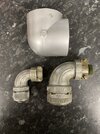
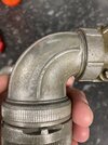
If you are looking for reference picture and measurements, I currently have the larger cannon elbow, smaller cannon elbow which are both originals, and also the centre elbow as I am making a casting of them , can take a some close ups and measurements if you want them?I spent the night modeling the two "CANNON" elbows used on the top and bottom of the Flux. I'm not an expert, but I believe these were some sort of vintage computer connector? I'm ballparking these based on limited imagery I can find. But they are way closer than what I had. The big fat top elbow is a modified PVC elbow. Close enough for me.
View attachment 1412651View attachment 1412648View attachment 1412649View attachment 1412646View attachment 1412650
Attachments
Thank you, that's very generous. I think I'm done with mine but I'm sure others here would benefit from that.If you are looking for reference picture and measurements, I currently have the larger cannon elbow, smaller cannon elbow which are both originals, and also the centre elbow as I am making a casting of them , can take a some close ups and measurements if you want them?
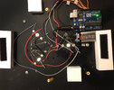
I did. This was my first project using an arduino. I found the code needed online and really just had to drag it onto the board. I could share the code here if that's helpful.this is amazing!!!.. im keen to take the plunge making one but really dont know much about the electronic side.. did you use an Audrino board?
ozisa
Well-Known Member
yeah that would be great!, do you know if there are any wiring diagrams about what does to where?I did. This was my first project using an arduino. I found the code needed online and really just had to drag it onto the board. I could share the code here if that's helpful.
Here's the Arduino Sketch:
// Flux capacitor chase sequence
int pinled2 = 13; // first ring
int pinled3 = 12; // second ring
int pinled4 = 11; // third ring
int pinled5 = 10; // fourth ring
int tim = 120;
void setup()
{
pinMode(pinled2, OUTPUT);
pinMode(pinled3, OUTPUT);
pinMode(pinled4, OUTPUT);
pinMode(pinled5, OUTPUT);
}
void loop()
{
digitalWrite(pinled2, HIGH);
delay(tim);
digitalWrite(pinled2, LOW);
delay(tim);
digitalWrite(pinled3, HIGH);
delay(tim);
digitalWrite(pinled3, LOW);
delay(tim);
digitalWrite(pinled4, HIGH);
delay(tim);
digitalWrite(pinled4, LOW);
delay(tim);
digitalWrite(pinled5, HIGH);
delay(tim);
digitalWrite(pinled5, LOW);
delay(tim);
}
Works.
Last edited:
ozisa
Well-Known Member
great stuff! will give this a go I'm thinking , thanks for you help!Sorry, this is the best I have. Essentially each "ring" of leds is wired together and connected to one of the input pics (9-13) on the arduino, All the negatives on the LEDS go to ground.
I can't leave this thing alone. With access to recent images of the two Cannon elbows and the vintage PVC elbow, I dove back in to my files to push these even closer to reality. Will be printing tonight.
View attachment 1461829
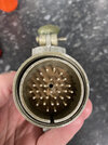
View attachment 1461840If it’s any help here is the end casted screw cap.
THANKS! Yeah, I'm getting close. Keep in mind there were MANY different versions of this part, each with some subtle differences. But the basics geometry is the same. It's a little ridiculous working this hard on this tiny retail that is ON THE BACK of the elbow that faces the wall
")
s
Last edited:
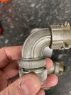
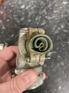
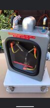
So the first elbow off the printer is the Big Fatty. This is similar, but also quite different from a stock PVC elbow. It's not painted yet but fits right into place. And yes, I finally got up the nerve to cut "The Notch" out of that back top piece of my Stalin enclosure so this piece fits properly as the screen used one did.


They look amazing! You don’t by chance happen to have the two other top attachments?, the black and yellow ( left) and blue,black,silver,gold( right) I have a cast version but have not attached it as it way to large. I looking to replace them to finish off the buildSo the first elbow off the printer is the Big Fatty. This is similar, but also quite different from a stock PVC elbow. It's not painted yet but fits right into place. And yes, I finally got up the nerve to cut "The Notch" out of that back top piece of my Stalin enclosure so this piece fits properly as the screen used one did.
View attachment 1461910View attachment 1461911View attachment 1461912View attachment 1461913
Can you share some pictures of what you’re asking about?.They look amazing! You don’t by chance happen to have the two other top attachments?, the black and yellow ( left) and blue,black,silver,gold( right) I have a cast version but have not attached it as it way to large. I looking to replace them to finish off the build
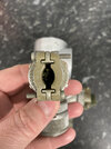
I have circled the ones I’m missingCan you share some pictures of what you’re asking about?.
Attachments
Thanks! I’ve seen the one in the right before but never seen the one in the left. Really cool. Are there any screen grabs from the film where you actually see these? I know the details changed from firm to film, but I’m curious about the authenticity of those connectors.I have circled the ones I’m missing
Similar threads
- Replies
- 20
- Views
- 1,904
- Replies
- 0
- Views
- 359
- Replies
- 4
- Views
- 609
- Replies
- 4
- Views
- 903