Electronics help needed!!

Mr. Nagata

Sr Member
RPF PREMIUM MEMBER
I'm trying to figure this out for a little project I'm doing. Help would be greatly appreciated. I have this servo controller board seen here:

board1.jpg


It runs off 9-12 VDC. Here is the power port with a little power diagram to the left of it:

board2.jpg


Here is a power plug that I got from radio shack that connects to an AC adapter:

board3.jpg


I can run this board by plugging the adapter into the wall. But I need this thing to be battery operated. I have an 8 cell AA holder that should be good for 12 volts. I was planning on wiring this battery pack to the pictured radio shack plug. However, I have no idea which wire runs to the positive and which wire runs to the negative:

board4.jpg


I'm assuming the wire with the text on it is the positive, but I'm not sure. I want to make doubly sure I'm connecting the battery correcty before I turn this thing on in case if fries the board or something. That would be a bummer.

So just to be clear, my question is, which wire (A or B) should be connected to the positive lead on the battery pack?
 
How would you use a continuity tester to check which side is positive and negative?

Sorry, I'm an electronics dunce :confused
 
Well being a radioshack power adapter the head comes off and you flip it around to reverse polarity, from the looks of it you have the center as + (confirm with your power adapter instructions), if you look at your pc board it also indicates center + or at least it appears to...

So what you are going to do is remove the tip (pay attention to it's orientation) put he continuity tester in the center of the tip and see what leg has continuity, that will be the + side...

Or you can touch the outside of the plug and see what leg is - ...
 
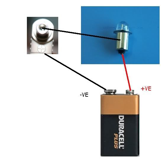
To do a simple continuity test you only need a few bits of wire a battery and a bulb. You could probably take the bulb and battery from a flashlight you have at home. Here is a very crude and simple diagram.

continuitytest.jpg


Basically put one piece of wire from the +ve of the battery to the +ve of the bulb.

Put one wire from the centre of your plug to the -ve of the light bulb.

Take a wire from the -ve of the battery and touch it on either of the two wires you think may go to the centre of the plug head.

Whatever one of the two points that lights the light bulb will be the one that goes to the centre positive.

Hope that makes sense.

exoray is also correct the centre should currently be set +ve on both supply and board. I would also think the wire with text should be +ve but the continuity check will confirm this.

Chris
 
You guys are awesome!!!

Here's the thing. I know that the orientation that the plug is currently in is correct (i.e. center positive). I know this because the diagram states that the board is center positive and I've tested the whole setup with the adapter plugged into the wall and it works fine. What I don't seem to know is which of those wires that runs into the plug is the positive lead and which is the negative. Should I just connect the wires to my battery pack and do a continuity test then? If it's wrong, I can disconnect it and reverse it.
 
If you know the plug centre is the positive you just need to know which pin of the two runs to the centre plug.

I presume when you remove the plug there are two pins hanging down which plug into the cable side.

Like in your photo the right hand pin will go to cable with text left hand to plain white cable.

If you do the light bulb continuinity check on your plug like in the diagram the bulb will light when either the left of right pin are touched that will tell you which cable is positive.

Chris
 
Did it. Figured it out. I can run the board off a 9 volt battery now. Thanks a lot for the info!
 
Back
Top