DSKY Apollo Guidance Computer

spodokomodo

New Member
With the 50th anniversary of the Apollo 11 moon landing coming up later this year, I have decided to make a replica of the Display Keyboard (DSKY) from the Apollo Guidance Computer (AGC). I was inspired by Curious Marc on his youtube channel. He is working part of a team that are trying to get an original Apollo era AGC (missing the DSKY) up and running again.

A quick search brought up the "open DSKY project". I was almost ready to purchase one of their kits, but after doing some more research I concluded that it wasn't accurate enough for me - it is more of a function replica than a true replica - plus, I realised that researching, designing, problem solving and building my own was much going to be much more interesting - The fun is in building the replica DSKY, not owning it.

So where am I at? First, I have transcribed the drawings I could find into Fusion 360 I have made a few modifications (thickening parts) to make sure that the model can be 3D printed. I have now printed all the parts and worked my way through most of the problems so I have a rough fit model put together.

I've included some photographs, but I only have a phone camera (and poor lighting) so I will supplement this with screen shots of the CAD model (I havent got the patience for proper renderings)

The next step is to take this apart for sanding, painting, finishing etc. While I have the DSKY in parts I intend to document each sub-assembly in an individual post.

Ultimately I intend release the 3D files and BOM to the community, but won't do this until I have a completely assembled unit incase I need to make any changes.

I will try to include all of the references I use as it may help if someone wants to make a their own more accurate version.

--

There are plenty of photographs of the DSKY internet, but you need to be carefull as many of these are of other replicas - I found some of the best photo resources are auction companies who were selling non-flown DSKYs (I won't link to the photos here in case of copyright problems, but they are easy to find).

A good overall resource is the Virtual AGC project, which has extensive documentation on the various versions of the DSKY/AGC with links to an incomplete set of original NASA/MIT/Raytheon drawings. These are a mixture of the block 1 and block 2 DKSY drawings and cover various versions and modifications made to the DSKY over the length of the Apollo program.

Fran Blanche, on her youtube channel, has a long term project to remake the display part of the DSKY using the original manufacturing processes. There is a video (Apollo AGC DSKY Display Project, Pt.1) where she has the opportunity to partially disassemble a non-flown DSKY. This was really useful, being able to see the internal components as physical objects rather than just the scanned engineering drawings.

Reference:
Open DSKY project - https://opendsky.com
Virtual AGC project - Virtual AGC Home Page
Virtual ACG project documentation - Virtual AGC Project : Free Texts : Free Download, Borrow and Streaming : Internet Archive
Curious Marc - CuriousMarc
Fran Blanche - Fran Blanche
Paper model - DSKY (DISPLAY KEYBOARD APOLLO GUIDANCE COMPUTER (AGC) FROM LM-5 - MODEL ART CRAFT KIT 1:1
Carl Claunch - Rescue 1130: 2014 Pickup of an IBM 1130 System and More

RPF threads:
Apollo LEM-5 DSKY/AGC
Has anyone built a replica DSKY from the Apollo Guidance Computer? >>

dsky0.png dsky1.png dsky2.png dsky3.png dsky4.png dsky5.png dsky6.png
 
Housing, Front

I found that this is the key piece to building the DSKY as most other sub assemblies build of this one. This is created using drawing "2004918 Housing, Front" (AGC Engineering Drawings, Batch 2 : MIT Instrumentation Lab : Free Download, Borrow, and Streaming : Internet Archive).

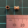
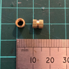
I split this plate into two plates to make 3D printing simpler with alignment holes added to aid gluing (these allow pins to be made from 1.75mm filament). I have used threaded inserts for the screw holes as I don't like to screw directly into plastic especially if I anticipate having to take something apart too often. The threaded inserts (M3 x 6mm) are intended to be fit from the opposite side of screw (whenever possible) so that they don't pull through when tightened. Spitting the plate in to two parts helps these be embedded inside.

Front cover mounting holes are moved to be 0.17in (originally 0.15in) from edge of front, to give a bit more material for the threaded inserts to bite into - this is the first sacrifice of accuracy for printability and has a few knock-on effects to the accuracy of other parts (particularly the Front Cover).

Bottom cutout is redesigned for strength and easier printing. The original has much thinner walls in some places, this piece needs to provide strength for the keyboard and is generally the strength piece of the device (I printed this part with 40% infill). I kept the material thick and simplified the design by removed internal component mounting point that are not needed.

HousingFront0.png HousingFront3.png HousingFront2.png HousingFront1.png HousingFrontInserts.png 3x6insert.png
 
Housing, Rear

The rear housing is build from a couple of boxes that are held together with screws. In-between these parts and the front housing are a couple of gaskets (the white parts). Once again I removed any un-needed internal mounting parts. The two gaskets on the real DSKY are used to pressure seal the DSKY as it is internally potted and then filled nitrogen (?) - I won't be doing this part, so the gaskets will be used as mount plates for my internal electronics, they are simple parts to reprint when changes are needed compared to the main housing parts. There is plenty of space inside the box for the electronics, so I won't need to build an external AGC.

The housings are held together with M3 x 6mm threaded inserts and an additional 8 M4 x 6mm are used to connect the front housing. The M4 inserts have a larger thermal mass compared to the M3 inserts and I may have applied too much heat for too long on a couple of them. This caused the PLA plastic to pull back a little - I fixed this by filling the gaps with superglue. Non of the screws/inserts in the DSKY are supporting a significant load so they won't need to be tightened too much - I think the fix will be OK for my needs.

I do feel a bit wrong using metric fixings on a project that was famously completed in imperial units - metric screws are easier for me to find in the UK, but I'm sure the M3 and M4 fittings could be swapped out with their 4-48 and 8-36 imperial equivalents (?)

The brass coloured fitting at the back is where the DSKY electronics connect to the main AGC. This is where I will connect my power etc. The part at the moment is a placeholder until I decide what connections I need it to do. I managed to model and print the threads so the bolt is actually used to secure the part.

HousingRear1.png HousingRear2.png HousingRear3.png HousingRear4.png HousingRear5.png HousingRear6.png HousingRear7.png HousingRear8.png 4x6insert.png
 
Front Cover

This is the least accurate part as I thickened it up internally a little to make it stronger. The mounting holes that were moved on the front panel allow for thicker screw posts. The spacing between the keys has been thickened slightly.

There are several drawings of the front cover with slightly different apertures for the indicator and display panel (I could just be reading the drawings incorrectly) - I suspect that I have drawing from several different revisions mixed together.

Overall I thickened up the internal parts to make the part more robust

FrontCover1.png FrontCover2.png FrontCover3.png FrontCover4.png
 
Adaptor Plate (and gaskets)

This piece mounts on to the front housing and provides fixing points for the indicator and display modules. The original part has a lot more internal structure that holds multi-pin connectors that allow the modules to be swapped in an out - I didn't need this so I removed it.

There are two identical gasket parts, I only show one in the pictures - I guess the could be made different as they require a different set of holes for the top and bottom mounting - but as these are unseen is easier to have one common part.

The part interfered slightly with the modified front cover screw posts, so I have notched the bottom edges slightly to provide some clearance - this is hidden completely when the cover is attached.

AdaptorPlate0.png AdaptorPlate1.png AdaptorPlate2.png AdaptorPlateInserts.png
 
Keyboard

This is the part I am least happy with - because I have chosen to keep the switch holes in the Housing Front plate the same as the original DSKY I now have to deal with the problem of adding the keyboard. The vertical and horizontal rib details in the keyboard area turned out to be helpful as they ensure the keyboard connects accurately to the front plate.

Early on I decided to go with cherry keyboard switches as they had a location for an LED and I assumed printing keycaps that attached would be simple (I was wrong). They keyboard is attached by 5 adapters that screw in from beneath, but still allow the wires to pass through

The idea is to use a MCP23017 i2c 16 input/output port expander to create a keyboard matrix and pass the wires down through the holes to a custom PCB beneath. I will add JST connectors to each switch so that they can be easily disconnected. In hindsight I should have gone for a PCB on the top site of the front plate so I only have to pass 4 wires down (VCC, GND, and the two for i2c). I will probably redesign the keyboard as some point, but I have something that is good enough for now.

Keyboard0.png Keyboard1.png Keyboard2.png Keyboard3.png Keyboard4.png Keyboard5.png keyboard6.png
 
Keycaps

I could just print blank keycaps and attach stickers for the labels, but this wouldn't give me illuminated keys. At this point I have tried about 10 different methods for printing the keycaps.

I need to use transparent filament to allow the light to pass though. The clear PETG I have has has a little too much give so it doesn't want to connect firmly to the cherry switches, plus it struggles to print sharp edges. The clear PLA I have is a little too brittle so the keycap stem breaks off. I was reluctant to buy any other filament so I didn't try any other materials.

I have finally settled on a composite keycap - a basic shape that connects to the Cherry switch, a clear plate with the text and then an additional plate on top with the black key surface. This is far from ideal as it misses out the internal shape of O, 8, R etc, but I have touched these in with black paint. To make the letters more visible without the back light on I added a thin layer of white paint to the key text before assembly.

I suspect printing with a FDM printer isn't the best way to go, but for now I have a rough set of keys that I can use.

I couldn't find any information on the exact form used for the keys so I made my best guess - if anyone knows the correct font, please let me know and I will redo these.

The keyboard font has a distinctive 3 and 2 shape which looks similar to Gotham, but not quite (Gotham Font Family | Download Free Fonts for Desktop and Webfonts). Circular Std (Circular Std Font Family | Download Free Fonts for Desktop and Webfonts) is also a reasonable match, but I found Baroil Bariol Font Family | Download Free Fonts for Desktop and Webfonts) gets the 7 nearer so I have used that for now - the text look OK in bold, but the numbers would benefit from a semi-bold, which isn't available, so I added a 2pt outline to thicken them a little.

keycap0.png keycap1.png keycap2.png keycap3.png keycap4.png
 
Squawk Box, finally a true prop replica...

I've noticed that others that build DSKYs have added a speaker that plays back NASA control room audio highlights - I liked the idea of doing this, but didn't want to add a speaker port to my case design. A bit of research (YouTube v=q0ewDH18JuA) revealed the Tandy SP-150 speaker that they used for a prop in the Apollo 13 movie.

I managed to find one that was cheep enough on e-bay, "working, but with minor cosmetic damage". From the listing photograph it looked like a minor scratch on the front grille plate right where the NASA logo would go - this was going to get covered up anyway so I bought it.

When it arrived the damage was a significant dent that bent most of the front plate about it enough to be noticeable. The speaker front grill plate is glued in but it looked like I was going to make more damage taking it out. My solution was to model and print a form piece of the negative space from the front, then by removing the speaker cone I could hammer it against this form from the inside to knock the dent out - worked perfectly!

As I had already don't most of the work to make the front grill I just carried on and modelled the whole speaker.

I then made a separate version that would accept a cheep bluetooth speaker I had lying around and printed this in a dark grey and silver filament - the colour looks close enough that I don't think I will need to paint it, I found a nasa logo and printed a small plate to hold it.

Ive uploaded the basic model files including the fusion 360 and step versions to thingiverse (Apollo 13 Squawk Box by spodokomodo) as you will probably need to modify the file a little to suit your choice of speaker. I printed the case part of mine in two half as it was a quicker print and removed the need for support. I used M3 screw and M3 x 6 threaded inserts.

squawk0.png squawk1.png squawk3.png squawk4.png squawk5.png squawk6.png
 
Excellent work! I started a DSKY replica project some time ago, but unfortunately had to stop working on it. I'm eagerly looking forward to reading about your progress.
 
I've created some fonts that may be useful in creating graphics for the DSKY. See ehdorrii/dsky-fonts

Thanks Gene, those fonts look so much closer than the temporary font I've been using.

I will update my files for when I do my next update - I have more parts nearly done, but I'm stugling with free time at the moment

(You know how it is, once spring/summer comes round all spare time is spent on the house and garden)
 
This thread is more than 4 years old.

Your message may be considered spam for the following reasons:

  1. This thread hasn't been active in some time. A new post in this thread might not contribute constructively to this discussion after so long.
If you wish to reply despite these issues, check the box below before replying.
Be aware that malicious compliance may result in more severe penalties.
Back
Top