Limited Run DaveP's Obi Static Parts Run 2022/23 (Sign-Up Closed)

One of my original parts uses a choke- made by Chris several years ago. And no spacer. It holds firm - I should have got more from him at the time.
All I use is an M6 rod all the way through. No butchering of the handwheel. I had cones made that fit the M6 thread to fit the BP. All good nothing under the clamp other than that bolt.
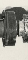
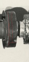
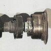
That's cool that you made it work. The only problem with not having a spacer though, is that the grenade doesn't sit on the clamp tabs. It's close, but for it to sit at the correct depth, it doesn't go in quite that far. So it does need a spacer of some sort.

GRENADE DEPTH.jpg


There's no butchering of the handwheel going on. The carriage bolts that I'm having made will fit the square hole in the brass part of the pommel.

I've left the cap off, because it wasn't present on the actual prop. It does still fit over the head of the bolt though if people prefer the look.

Having all the (very nearly) final models in the scene together has been really useful for working out some of these details. Having lined up the correctly scaled pieces with the reference photos, it's clear now, that had the cap been present, it's edge would be visible due to the height that it sits at when installed.

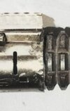
I guess that's quite a controversial and important revelation, so here's a picture to show what I mean:

POMMEL CAP.jpg


Looks amazing Dave! would it be possible to be put down for the 2 part balance pipe and the resistors and washers? What's the threading you plan to go with for the insert in the balance pipe?

Thanks Martin! Absolutely. It's not necessary to order the full thing. I can put you down for those. Thanks!

For the carriage bolts, I'm hoping to have them made as standard M8 with 8mm head block to fit the metal part of the handwheel. These aren't available off the shelf at the length needed, so I'll be having them made specially.

Is it too late to sign up? If not, I’m interested!

Hi Derek. Not too late, no. Just updated the list now. Thank you :) 
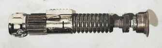
I've seen your DM by the way, and just catching up on messages now. I'll reply shortly. Thanks again (y)

I’m definitely in favor of using the cut down flash hider inside the clamp. That’s what I’ve kind of always assumed they did to be honest. Why take it off and then add a spacer back in if cutting it works as well as it seems that it does?

Indeedy. I've heard from quite a few people now who have done this with their vintage parts. That's commitment! :eek:

In fact it was pointed out to me just recently that many vintage flash hiders are near impossible to remove from the muzzle. So in some cases there isn't even the option of removing it.

The more I look in to it, and the more I hear about it, the more I'm convinced that this could actually be how the original prop was put together.

We'll never be certain of course, and it'll be optional for those who aren't keen.
 
**UPDATE**

Hello everyone. It's been a while, and I just wanted to give you all a quick update as to where things are up to....

This won't be a picture heavy update I'm afraid. I'm currently in the process of drawing up the technical drawings for the various manufacturers and machinists, which obviously, I won't be sharing! :p

I'm making good progress on those and should be ready to start sending them out for quotes VERY soon!

I just wanted to make everyone aware that a lot of work is being done behind the scenes and things are moving forward.

Obviously, the fact that I'm at the tech drawing stage, implies that all design work is now final and the models won't be undergoing any more changes! (y)

Following my previous update though, I did make some small, but important changes to the models based on the observations of community veteran and Static Obi expert, teecrooz! Thanks so much for being so generous with your time, Chris (as always) and for helping to really focus in on these small but important details!

The wind vane has undergone a complete remodel...

New Neck.jpg


Rather than basing the profile of the ring on the usual Cotton Powder Co version, it is now based on the Roburite & Ammonal style.

In actual fact, it's been remodelled to match the prop reference images. It just so happens, that the Roburite rings are ALWAYS the correct profile, so for the above render, I've shown how that will look.

Hard to say which text is present on the prop, as I believe it is covered with tape. I can't share my best references, but I can tell you that there are, without a doubt, two edges present at the point where the groove for the lip begins. One being the edge of the metal, and the other being the edge of what I believe to be tape.

As I'll be stamping these myself, I'm more than happy to include whichever stamp people prefer (or no stamp).

You may notice the small tab that is protruding from the top of the wind vane. This was missing from my previous model, but will be present on the final thing.

There are some other VERY interesting observations that I have made when comparing my models with the actual prop. There is a great deal of variation in some of these vintage parts as you may know. I have come to learn of some very specific details that set those used on the prop apart from many (most??) that crop up in people's collections.

The point of this run after all, is that it is a replica of the prop, and not merely a vintage parts replica. Any details that are specific to those on the prop will take precedence over those which are perhaps more prevalent.

Rest assured that where I have deviated from my previous models, in order to better match what is seen on the prop, I have double (triple!) checked that I am not mistaken (or going crazy!). I've also run my thinking by others behind the scenes too. (y)

The details I'm speaking of are very minor adjustments, but they will be unique to this run. For that reason, I'm going to keep them to myself for the time being.

Please rest assured that I'm now 100% happy with how everything is lining up with the references and that as soon as I'm done with the drawings, they'll be on their way for quotations. :)

I'm now (as recently as last week) 100% happy with material specs for the parts too. I wish I could share with you the lengths I've had to go to to reach this point! The number of people I've had to reach out to, some helpful, some not so... It's been a fascinating and all consuming journey, which unfortunately, I will have to keep to myself (for the time being at least!). I hope you'll understand, and hopefully trust that the due diligence has been done, and that the people who have been kind enough to help REALLY know what they're talking about!

For now, I'll be dropping back off the radar whilst I work my way through the drawings and as soon as I have quotations back, I'll finally update the thread with prices going forward.

Thanks again for your patience everyone! It really is very much appreciated!

All the best and MTFBWY-A

Dave
 
Hi Dave

DISCLAIMER: I've never held any of these real parts in my hands. What I'm about to say is based on me closely following the research here on real parts and the construction of this saber since about 18 years ago, and based on the replicas that I've purchased here over that time frame. Your 3D modelling, your reference material and the help you have been getting behind the scenes is clearly superior.


I want to post this photo again so we can think about what is visible through the two tab holes and one slot in the Graflex clamp.

1664995402434.png


First, let's look at the left tab hole. I believe I see something on the left edge of that hole, and I've read others here on the RPF mention the same. Maybe that's just tape, but the left tab hole looks less open than the right tab hole. One theory (that I personally believe) is that either a muzzle choke or a flash hider (that was cut shorter) was first inserted into the central portion of the clamp and then the booster was screwed onto the muzzle choke or flash hider so the two left tabs in the Graflex camp were captured between the booster and the muzzle choke or flash hider.

Second, look at the slot and the right tab hole in this Chronicles photo. They look totally empty and dark to me. If your 3D modelling of a hypothetical flash hider inside the clamp shows any part of that flash hider visible through that slot and right tab hole, then I believe we can rule out the theory that there was a cut-down flash hider in there. I don't know the answer, but it would be really interesting to see how things line up using your 3D model - both with the flash hider fully screwed into the booster or with the flash hider only partially screwed into the booster in order to capture the two left tabs, as I explained above.

Third, my grenade is a replica so take this with a grain of salt, but my replica grenade rests on the right Graflex clamp tabs with no spacer inside that clamp, and everything lines up perfectly on the outside. (Perhaps the cap was still on the end of the grenade on the prop, but would that even help in this regard? Perhaps the grenade is stopped by the tiny screws through the clamp. Perhaps some grenade variations simply have a thicker bottom until the first ring groove is cut in the frag body.) I like having no spacer and nothing but a threaded rod up the middle because I feel that having blackness in those three holes through the clamp is most authentic relative to the Chronicles photo. I've even blackened my threaded rod so nothing silver reflects any light from within.

All I'm saying is that now that you have all of the parts very accurately modelled, you can play around with several different assembly methods virtually and check how things look through these three 'windows' through the Graflex clamp (just like you recently concluded that the cap is not on the handwheel). Sounds like a fun experiment.

Chris
 
Last edited:
Also from that picture, I'm now (for the first time) seeing what looks like two or three layers of tape around the ring. I tried to track the edges using my photo editor. Sorry for the poor editing quality
 

Attachments

  • Screenshot_20221006-011552_Gallery.jpg
    Screenshot_20221006-011552_Gallery.jpg
    744.3 KB · Views: 102
  • 20221006_012515.jpg
    20221006_012515.jpg
    313.6 KB · Views: 92
Also from that picture, I'm now (for the first time) seeing what looks like two or three layers of tape around the ring. I tried to track the edges using my photo editor. Sorry for the poor editing quality.

Wish this shot was in color o_O I wonder if it could be something like darkened/oxidized copper tape (or painted over)
 
Hi Dave

DISCLAIMER: I've never held any of these real parts in my hands. What I'm about to say is based on me closely following the research here on real parts and the construction of this saber since about 18 years ago, and based on the replicas that I've purchased here over that time frame. Your 3D modelling, your reference material and the help you have been getting behind the scenes is clearly superior.


I want to post this photo again so we can think about what is visible through the two tab holes and one slot in the Graflex clamp.

View attachment 1623961

First, let's look at the left tab hole. I believe I see something on the left edge of that hole, and I've read others here on the RPF mention the same. Maybe that's just tape, but the left tab hole looks less open than the right tab hole. One theory (that I personally believe) is that either a muzzle choke or a flash hider (that was cut shorter) was first inserted into the central portion of the clamp and then the booster was screwed onto the muzzle choke or flash hider so the two left tabs in the Graflex camp were captured between the booster and the muzzle choke or flash hider.

Second, look at the slot and the right tab hole in this Chronicles photo. They look totally empty and dark to me. If your 3D modelling of a hypothetical flash hider inside the clamp shows any part of that flash hider visible through that slot and right tab hole, then I believe we can rule out the theory that there was a cut-down flash hider in there. I don't know the answer, but it would be really interesting to see how things line up using your 3D model - both with the flash hider fully screwed into the booster or with the flash hider only partially screwed into the booster in order to capture the two left tabs, as I explained above.

Third, my grenade is a replica so take this with a grain of salt, but my replica grenade rests on the right Graflex clamp tabs with no spacer inside that clamp, and everything lines up perfectly on the outside. (Perhaps the cap was still on the end of the grenade on the prop, but would that even help in this regard? Perhaps the grenade is stopped by the tiny screws through the clamp. Perhaps some grenade variations simply have a thicker bottom until the first ring groove is cut in the frag body.) I like having no spacer and nothing but a threaded rod up the middle because I feel that having blackness in those three holes through the clamp is most authentic relative to the Chronicles photo. I've even blackened my threaded rod so nothing silver reflects any light from within.

All I'm saying is that now that you have all of the parts very accurately modelled, you can play around with several different assembly methods virtually and check how things look through these three 'windows' through the Graflex clamp (just like you recently concluded that the cap is not on the handwheel). Sounds like a fun experiment.

Chris
Hi Chris.

Interesting ideas, and I see what you mean about the choke/hider sitting on the tabs. It's obviously possible, and would affect the length of the hider if it was used. But I actually think that what you're seeing at the edge of the left hole, is at the surface level. In fact, I think it could well be the tab itself, having been straightened out somehow (possibly). The problem with resting the choke at the mid point of the clamp, on those two tabs is that it wouldn't be particularly stable. Or at least, not as stable as having it screwed all the way in I don't think (in my mind at least)... Also, my current setup has the cotter pins hooked over the flange of the choke. I'm not sure how they'd function otherwise. Perhaps, they could in theory be caught between the muzzle and the choke, and held in place by the choke.

There is still a certain degree of speculation with regard to spacer setup, and it's going to be very difficult to prove one way or another.

I have already takien a look at the position of the spacer through the clamp windows and I can tell you that it IS visible, as the rod itself would be too without it, but as soon as you add any lighting/shadows to the models, they disappear in to darkness.

I've tried the inverse too and tried to brighten the reference image and play around with the levels/curves, to try to get a glimpse of what's hiding under there. It's just too dark unfortunately.

But as Mr Sagan used to say, "absence of evidence is not necessarily evidence of absence". Or something like that.

Unfortunately, I'm going to have to go with the solution I have now as I just don't have the time to go back over it. With it being open to interpretation to a certain extent, I'm going to have to run with it and hope that people are happy with it.

It is still optional of course, and a couple of washers/nuts positioned on the bar would do the same job if preferred. Or people are welcome to come up with their own solutions too.

Hope you understand, that there is a fair amount of work ahead of me still with the remaining CAD drawings, and if I keep going back to the things I've drawn a line under, people are going to be waiting a looong time for the run to happen.


From that picture I'd say it looks like the emitter is soldered/brazed onto the grenade

100% I'm pretty sure that what we see in the images is a combination of dings/dents/solder (y)

Also from that picture, I'm now (for the first time) seeing what looks like two or three layers of tape around the ring. I tried to track the edges using my photo editor. Sorry for the poor editing quality

Exactly what I'm seeing, Chris! Thanks for sharing :)

Wish this shot was in color o_O I wonder if it could be something like darkened/oxidized copper tape (or painted over)

I wondered the same thing, Bryan. just based on how smooth it is, my fist choice was PVC/electrical tape, maybe painted like you say??

The best we've got for the colour is this I guess:

OBI DS.jpg


Certainly looks to have a dark brownish colour to me, rather than just being plain black insulation tape.
 
tried a bit of retouching in PS and brought a bit more colour in but best I can do with that old photo...to much magenta in this as well.. but another view on it
Nice! I considered overlaying the Tunisia photo over the top of the Chronicles ones and baking in just the colours, but the lighting in that particular image will be massively effecting the colours. That looks great though!
 
Curious. The solder/weld material on the balance pipe and windvene. The reflection and shadows look similar on the top edge of the clamp. There appears to be some foreign material between the grenade and the clamp, I've never noticed or paid attention to before. Has anyone wondered whether or not they tried welding the clamp to the grenade? Perhaps that isn't foil tape, but instead the clamp itself was damaged from the heat?
 

Attachments

  • emitter.jpg
    emitter.jpg
    48.6 KB · Views: 98
  • clamp.jpg
    clamp.jpg
    38.8 KB · Views: 95
Last edited:

Your message may be considered spam for the following reasons:

If you wish to reply despite these issues, check the box below before replying.
Be aware that malicious compliance may result in more severe penalties.
Back
Top