Daft Punk Guy-Manuel Helmet Build - Excessive LEDs and 3D Printing

ThreeFN

Member
Hi all. I've finally gotten around to making this thread.

I'll start with the short, image based version.

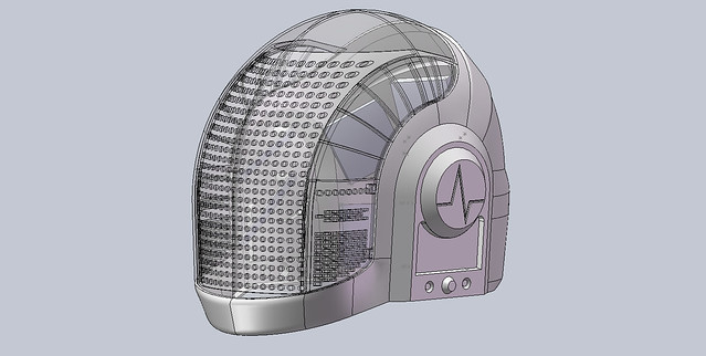
Back in October 2006 I started with this:


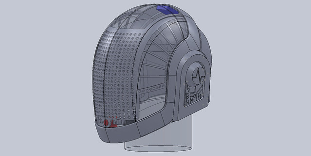
Which evolved into this:


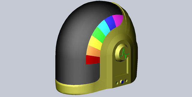
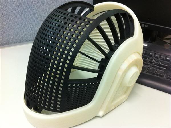
And finally became this:


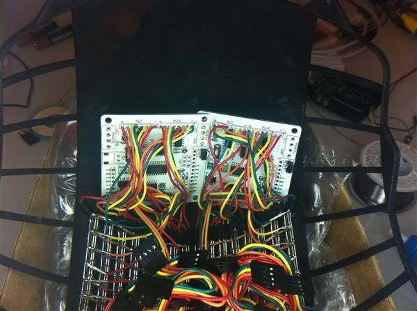
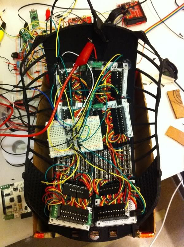
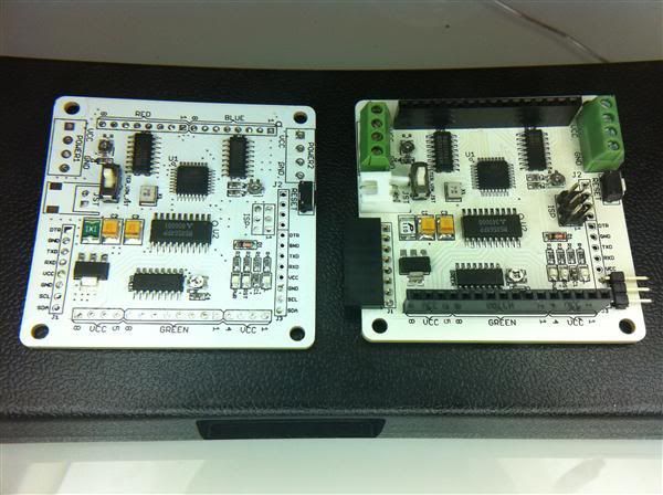
Which was then realized as this:

8.jpg


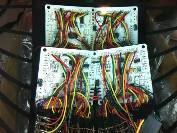
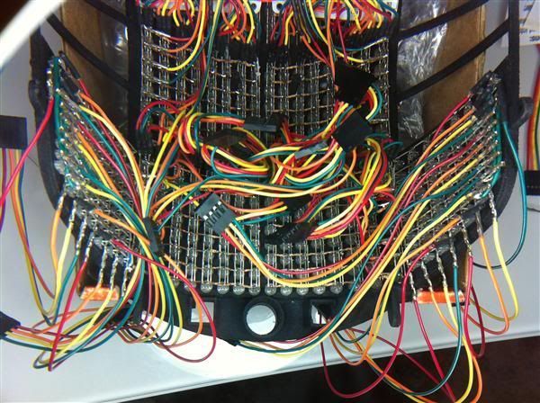
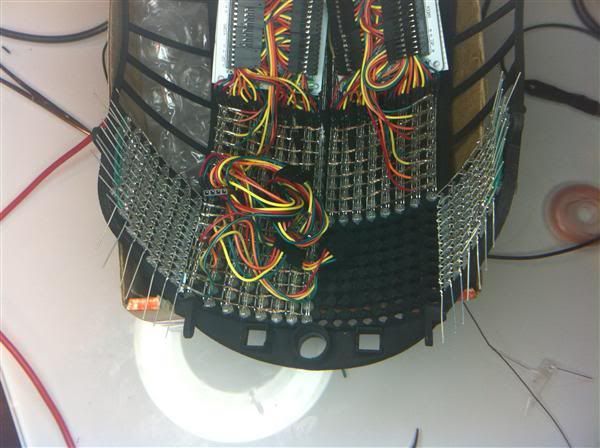
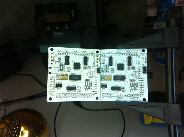
Which, after a lot of soldering, became this:

IMG_0602.jpg


And everything was generally slowed down by this:

IMG_0601.jpg


Well, her and the day job.

I started this project, technically, in October of 2006 as more of a challenge and 3D modelling exercise than an actual project and physical thing to be made. Of course, over the years as I got better at CAD and became increasing more interested in microcontrollers, and then I stumbled across the critical piece of electronic hardware I needed to start the project in earnest in July 2009.

I've detailed much of the electronics, software, and accomplishments with the LEDs via the my YouTube channel. I've also got a decent smattering in the PhotoBucket and Flickr Accounts. I'm also getting around to working on a build log-ish blog which at the moment largely details the design and design decisions in the project. I'll refer you to that lot rather than try and rehash everything in this thread. I'm sure Q&A will clean up the bits in between.

I'll finish with my most recent video.
I'd embed it better if I could figure out how.
 
Last edited:
So, where am I at now?

Right now, I've just finished the first stage of wiring some 'cheek EQ' extra lighting and I've decided that I need to strip down and minimize the rainbowduino LED control boards so that they take up less space. I've stripped down 5 of the 7 I use, and started work on wiring and installing the first two 'superleggera' rainbowduinos. The biggest pain so far has been that after you unsolder everything on the board, you have to go back and remove all the excess solder so the holes are clean. All I can say is thank engineers for the solder vac pump.

IMG_0766.jpg


Backside shot of with the two 'cheek EQ' sets of lights installed.

IMG_0769.jpg


Comparison shot between a stripped down rainbowduino and a standard one.

IMG_0770.jpg


The top two rainbowduinos with the power and data bridged between them.
 
Last edited:
That is insanely well done and your hard work shows,

once again I'm filled with envy when I see these sorts of builds


Well done! (y)thumbsup(y)thumbsup:thumbsup
 
Dude... This is unreal man. I am at a loss for words.

Well, um, I'm a wealth of words on the subject, but I don't have much to go on without a question :rolleyes

That is insanely well done and your hard work shows,

once again I'm filled with envy when I see these sorts of builds

Well done! (y)thumbsup(y)thumbsup:thumbsup

I do enjoy getting to the stage of knowledge and confidence with electronics and CAD so that you can (almost) build anything. The only downside is that when you think you CAN build anything, suddenly there's NOTHING TO STOP YOU wanting to build EVERYTHING.
 
Fantastic! This build is awesome. Your hard work really shows!!! I could never in a million years figure out any of those circuit boards and stuff! I APPLAUD YOU!!!!!!!!
 
Fantastic! This build is awesome. Your hard work really shows!!! I could never in a million years figure out any of those circuit boards and stuff! I APPLAUD YOU!!!!!!!!

Cheers mate.

Digital circuits really aren't all that bad, since, really, at the heart of them they only (really) have two states: on, and off.

For instance, PWM, the heart of most modern LED dimming, is just turning the power on and off faster than the eye can see. The ratio of on time to off time gives you the perceived brightness.

You just have to trust that a microcontroller can do a lot of simple things, but it can do them very, very, very quickly. So it can be made to look like it's doing a lot of complicated things.
 
Ive been following this over on TDC, and all I can say that hasn't already been said is 'BOUT TIME YOU MADE YOUR OWN THREAD! I love watching the build come together!
 
Ive been following this over on TDC, and all I can say that hasn't already been said is 'BOUT TIME YOU MADE YOUR OWN THREAD! I love watching the build come together!

Yah, wanted to get to a good point before starting my own thread. I'd like to be more consistent in my progress and life up til now hasn't really allowed that. We shall see about the future.
 
Wow holy crap i love it! Most outstandng dude! Lots of work but will pay off to the fullest. Also, i have a cat just like that, down to the orange highlights lol
 
Wow holy crap i love it! Most outstandng dude! Lots of work but will pay off to the fullest. Also, i have a cat just like that, down to the orange highlights lol

Yah, I'm pretty sure Freyja is a Maine (second part of this common American feline breed) moggie since she's only 10lbs. She makes noise for the sake of making noise, paws at my eyelids to wake me up, and her tale is a fur wrapped wrecking ball. But just try to say no to all that fluffiness.

EDIT:
Apparently, RPF finds the second half of this feline breed to be offensive and the word filter got it. Um, ok.
 
holy shiat, the all led guy helmet? THIS will be interesting ;)
looks really great so far!

Yep, lots-o LEDs. But as my signature says, I'm one-upping the original DP designs as much as possible. I've switched RGY (red/green, combined yellow) for RGB (red/green/blue, can make almost any color) for the main display.

The part that is still being designed/worked on is the side bars (blank spaces either side of the main display). These bits have been the most troublesome bit because they're a large surface area and I want them to be RGB as well. I think we've settled on a system that will work, I'm just waiting on the partner in crime to finish up the prototype. Work for him has gone rather skitzoid recently.

I'm fairly sure you'll be able to see this thing from space once it's done. In theory there's like 50W of LED power in the helmet.
 
This will be the BEST Guy helmet out there, no one will one up this :p

Eh, I don't know about that. Knowing me, I might do so in the future :behave

Minor-ish update. I've managed to hard-wire the top two matrices. It's rather fiddly. Takes ages to do and plenty of contortion of the hands. It reminds me of wiring the main display. Already managed to miss-wire one of the color banks. Not a great deal of fun to redo, but not as bad as I thought I would.

IMG_0772.jpg
 
And another update.

4 of the 7 rainbows wired up and 'installed.'

image1.jpg


And the cheek EQs are now wired.

image2.jpg


Next stage is the EQ wiring to the rainbow. I'm going to take a bit of break and work on the software for a bit. Not a whole lot of point wiring up the EQs if I don't have any code to test it with. Or at least one will need to be finished right after the other :confused
 
Most impressive. Even more so if you don't come from an electrical engineering background like I do. I can appreciate how much work this has been, impressive you went to the trouble of full animations with the LED array. The electronics part looks fun, but how the heck did you make the helmet itself? Print it with some obscenely expensive awesome tool?

Now real trick is, will you be able to wear the helmet and see through the LED array enough to use it?
 
Most impressive. Even more so if you don't come from an electrical engineering background like I do. I can appreciate how much work this has been, impressive you went to the trouble of full animations with the LED array. The electronics part looks fun, but how the heck did you make the helmet itself? Print it with some obscenely expensive awesome tool?

Pretty much. I have a very, very good friend who allows me access to a 3D printer. It's pretty much the only way to manufacture something of this level and complexity. Once you discover how easy it all is to just go from CAD to printed object, it's hard to go back.

Now real trick is, will you be able to wear the helmet and see through the LED array enough to use it?

Three components: CMOS camera, MAX7456 OSD chip, and Vuzix video goggles.

The camera is, well, obviously a camera. NTSC specifically.

That then feeds into a MAX7456 chip, which is a text overlay often used in security camera system for time stamping and the like. I use it as a heads up display to show me pertinent information about the whole system (what's running, menu tree, battery state, etc).

Then, to actually see any of this, I have a pair of video goggles mounted into the helmet.

It's not perfect, obviously. The view angle is pretty poor and a the clarity is only marginally better. But the Guy-Man visor is far too complex a curve to do a normal LED array like in a Thomas helmet (see Volpin's work for example).

My display is also RGB which means twice the wiring at a minimum. At last count I had to do at least 1,728 solder joints for this thing.
 
This thread is more than 8 years old.

Your message may be considered spam for the following reasons:

  1. This thread hasn't been active in some time. A new post in this thread might not contribute constructively to this discussion after so long.
If you wish to reply despite these issues, check the box below before replying.
Be aware that malicious compliance may result in more severe penalties.
Back
Top