Tone down !!!! Are you crazy !! Keep this beautiful build going to this fabulous standardSide Model
View attachment 1256833
-----
Normal Socket Head Screw, Hex Drive
M1.6 x 0.35 mm Thread, 4 mm
Quantity: 8
Available: UK Socket Head Cap Screws ISO 4762 (DIN 912) M1.6 in A2 Stainless Steel - Westfield Fasteners Ltd
View attachment 1256834 View attachment 1256835
Normal Socket Head Screw, Hex Drive
M2 x 0.4 mm Thread, 10 mm
Quantity: 18
Available: UK Socket Head Cap (Allen) Screw M2 x 10mm in A2 Stainless - ISO 4762 (DIN 912) - Westfield Fasteners Ltd
View attachment 1256836 View attachment 1256837 View attachment 1256838 View attachment 1256839 View attachment 1256840 View attachment 1256841 View attachment 1256842
Normal Socket Head Screw, Hex Drive
M3 x 0.5 mm Thread, 6 mm
Quantity: 8
Available: UK M3 Screw Unbrako Socket Head Cap (Allen) 6mm in Black - ISO 4762 (DIN 912) - Westfield Fasteners Ltd
View attachment 1256843
Low-Profile Socket Head Screw, Hex Drive
M3 x 0.5 mm Thread, 6 mm
Quantity: 4
Available: UK Low Socket Head Cap Screw M3 x 6mm in A2 Stainless - DIN 7984 - Westfield Fasteners Ltd
View attachment 1256844 View attachment 1256845
Flat Head Screw, Hex Drive
M3 x 0.5 mm Thread, 10 mm
Quantity: 10
Available: UK Unbrako Socket Head Csk Screw Full Thread M3 x 10mm in Black Oxide - ISO 10642 (DIN 7991) - Westfield Fasteners Ltd
View attachment 1256846 View attachment 1256847
Low-Profile Socket Head Screw, Hex Drive
M3 x 0.5 mm Thread, 16 mm
Quantity: 8 (These 4 for the fan, and 4 for the base mentioned bellow).
Available: UK Low Socket Head Cap Screw M3 x 16mm in A2 Stainless - DIN 7984 - Westfield Fasteners Ltd
View attachment 1256848
M4 x 0.7 mm Thread, 20 mm
Low-Profile Socket Head Screw, Hex Drive
Quantity: 10
Available: UK Low Socket Head Cap Screw M4 x 20mm in A2 Stainless - DIN 7984 - Westfield Fasteners Ltd
View attachment 1256849
M4 x 0.7 mm Thread, 35 mm
Low-Profile Socket Head Screws, Hex Drive
Quantity: 4
Available: UK Low Socket Head Cap Screw M4 x 35mm in A2 Stainless - DIN 7984 - Westfield Fasteners Ltd
View attachment 1256850
Normal Socket Head Screw, Hex Drive
M5 x 0.8 mm Thread, 10 mm
Quantity: 4
Available: UK Unbrako Socket Head Cap Screws ISO 4762 M5mm in Black oxide high tensile steel class 12+ - Westfield Fasteners Ltd
View attachment 1256851 View attachment 1256852
Bottom Model
View attachment 1256869
Low-Profile Socket Head Screw, Hex Drive
M3 x 0.5 mm Thread, 16 mm
Quantity: 4 (Counted Above)
Available: UK Low Socket Head Cap Screw M3 x 16mm in A2 Stainless - DIN 7984 - Westfield Fasteners Ltd
View attachment 1256870 View attachment 1256871
Inside Model
View attachment 1256872
Nyloc Nut Type T (Thin) M3
Quantity: 4
Available: UK Nyloc Nut Type T (Thin) M3 in A2 Stainless - DIN 985 - Westfield Fasteners Ltd
View attachment 1256873 View attachment 1256874
I don't know if this is too much detail, I'm having fun detailing the project! If its too much let me know and I will tone it down!")
You are using an out of date browser. It may not display this or other websites correctly.
You should upgrade or use an alternative browser.
You should upgrade or use an alternative browser.
Chappie - Head Project (3D Printed) - Build Thread / Picture Heavy / Finished! -> Page2
- Thread starter diogorsergio
- Start date
Thanks guys! I'll continue then

The electronics and the screws have arrived! I never did anything major with Arduinos, so this will be a good opportunity to learn! Need to connect the LCDs and some LEDs.

I'm following Kenobi's idea from his own build and using fibre cable and LEDs to light up some parts that were quite tiny to insert the LEDs themselves. I put this together just to see if it would work!

The fibre cable its for those 3 lights!

Found out I made a mistake when modelling the LCDs in Fusion360 to adapt the 3d part to them.. and they don't fit

I modelled the LCD's in Fusion360 based of a picture I found online, everything was right.. but I flipped the image and didn't noticed.. the SD card was now on the wrong side.. so it doesn't fit!

I rushed to it and fixed it! Now the SD card would have space to fit..

But made another mistake! I didn't account for the small chips behind the SD card.. only accounted for the SD card slot.. so it didn't fit either

Back to Fusion360!

I had to open the whole area so the LCD board would fit.

Now everything fits properly!

Preparing the model to print! Using Simplify3D

Ready to go to the printer!

It all fits properly now!

The SD cards have space.. and there's a gap for connecting the wires...

This is their position in regards to the whole setup!

I also managed to clear coat everything to protect the paint, it also gave the parts a nice shine to it!

I tried using super glue to give the impression that parts were welded together! It actually looks great!
The electronics and the screws have arrived! I never did anything major with Arduinos, so this will be a good opportunity to learn! Need to connect the LCDs and some LEDs.
I'm following Kenobi's idea from his own build and using fibre cable and LEDs to light up some parts that were quite tiny to insert the LEDs themselves. I put this together just to see if it would work!
The fibre cable its for those 3 lights!
Found out I made a mistake when modelling the LCDs in Fusion360 to adapt the 3d part to them.. and they don't fit
I modelled the LCD's in Fusion360 based of a picture I found online, everything was right.. but I flipped the image and didn't noticed.. the SD card was now on the wrong side.. so it doesn't fit!
I rushed to it and fixed it! Now the SD card would have space to fit..
But made another mistake! I didn't account for the small chips behind the SD card.. only accounted for the SD card slot.. so it didn't fit either
Back to Fusion360!
I had to open the whole area so the LCD board would fit.
Now everything fits properly!
Preparing the model to print! Using Simplify3D
Ready to go to the printer!
It all fits properly now!
The SD cards have space.. and there's a gap for connecting the wires...
This is their position in regards to the whole setup!
I also managed to clear coat everything to protect the paint, it also gave the parts a nice shine to it!
I tried using super glue to give the impression that parts were welded together! It actually looks great!
Attachments
Last edited:
Quick update.. to show some progress!

Quick prototyping of how I can get he fibre cable illuminated with a LED.

The final color will be green but this gives an idea. Just a simple LED inside a shrinkwrap with the fibre cables touching it.

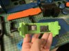
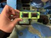
Since the LCDs have arrived.. I start working on them and see how can I display the Chappie Boot Sequence.. I never used Arduino much.. so I was learning as I went..

Converting bitmaps to bit arrays using (image2cpp).

Looks awesome!

Checking the quality of the display!.. for something so tiny.. amazing
Both displays wired to an Arduino.. at this point they were being driven by the same code.. this meant I couldn't do the sequencing of dots going horiontally from one display to the other.. and back around like in the movie..

So next I tried to wire each of them to their respective Arduino Nano, this way they could run separate code!

At this point I found out.. the displays in the real thing were square.. so I went back I tried to find something that could work better.

I ordered some ST7789's 240x240px from Adafruit!

Wiring them up!

Looking good! At this point I managed to get in touch with some of the concept artists that worked on the movie and asked about the boot sequence.. and they provided the right information about it! So now I only had to try and make it work with the Arduino.

It looked pretty cool! At this point I managed to figure out a way to connect both displays to a single arduino and target them individually..
Boot up sequence! Since they are running the same code.. one of displays was processing the code earlier than the other.. so there was a slight delay!

Time to get measurements and update the visor for the new displays!

Using Fusion360 and some of the promotional images from the Adafruit website!

They would fit... but just barely

I had to cut the mounting holes..so I did that.. and grinded the edges with a dremel.

Success! They still work!

Printed and tested!
Quick prototyping of how I can get he fibre cable illuminated with a LED.
The final color will be green but this gives an idea. Just a simple LED inside a shrinkwrap with the fibre cables touching it.
Since the LCDs have arrived.. I start working on them and see how can I display the Chappie Boot Sequence.. I never used Arduino much.. so I was learning as I went..
Converting bitmaps to bit arrays using (image2cpp).
Looks awesome!
Checking the quality of the display!.. for something so tiny.. amazing
So next I tried to wire each of them to their respective Arduino Nano, this way they could run separate code!
At this point I found out.. the displays in the real thing were square.. so I went back I tried to find something that could work better.
I ordered some ST7789's 240x240px from Adafruit!
Wiring them up!
Looking good! At this point I managed to get in touch with some of the concept artists that worked on the movie and asked about the boot sequence.. and they provided the right information about it! So now I only had to try and make it work with the Arduino.
It looked pretty cool! At this point I managed to figure out a way to connect both displays to a single arduino and target them individually..
Time to get measurements and update the visor for the new displays!
Using Fusion360 and some of the promotional images from the Adafruit website!
They would fit... but just barely
I had to cut the mounting holes..so I did that.. and grinded the edges with a dremel.
Success! They still work!
Printed and tested!
Last edited:
The pins come out the back..so they can be wired up.
With the front part of the visor, the size of the displays was perfect.
Side by side comparison with the old LCDs.
Next! I wanted to actually include an LCD in the back of the head. So I updated the original box, and modeled it to received an Adafruit display!.
Some studies of how I could keep the display agains the edge.
The display was bigger than what was needed.. so I used a front part to maskout only what was needed.
Side by side comparison with the old part.
Slight change of size... in some things.. but barely noticeable and it was worth doing by having the LCD!
The LCD arrived.. and it actually fits! first time..
Display agains the edget of the box
And used a small latch to keep it in place!
And finally side by side with the old one!
Wiring it up.. and playing around with Arduino code.. to display the images!
Made a small hole in the back for them to come out!
Painted the parts and connected the wires!
The LCD In action!
Screen grab from the movie.. I though since I'm doing all this work to include the LCD it would be fun to actually design these parts too.. and make them influence the LCD.
Updating the old parts!
CPU board where the guard key was inserted!
The memory slot!
So my idea was to use reed switchs... to change the LCD based on which boards plugged...
Reed switchs activate when theirs a magnetic field close to them.. so I included a slot for magnet in the end of the boards.. and made a slot to push the reed switchs.. up the part so they would be within distance of the of the magnets!
Here is a view with everything in their place!
The reed switchs and the 3dprinted slots..
Bending the legs down...
The switched are held in place my friction at this point.. but they will be held agains the slot with some screws.
The slots and switches in place!
Soldering some wires to the switches..
This way they could come all the way back!
And allow to be connected to the Arduino.
Thats it for now!
This is such incredible work and thanks for documenting it so well, its a really interesting read! I'm currently waiting on some LCD screens to finish my Chappie head build (no doubt I'll realise mine arent quite right and have to swap them out too ). It's interesting that you got in touch with the concept artists for the film. I'd be interested to hear about that in Pm's if you don't mind? Sayha
Shakeitdavey
Well-Known Member
I love CHAPPIE! - Can't wait to see this finished.
Thanks guys! Waiting on the stickers to finish this project! Already did some weathering and its looking great! Challenging project for me, but ended up learning a lot of new skills. I'll post the last update some time next week.
All the work I did on new 3d modeled parts, electronics schematics, arduino code for all three LCD sizes will be available for download.
Already did some weathering and its looking great! Challenging project for me, but ended up learning a lot of new skills. I'll post the last update some time next week.All the work I did on new 3d modeled parts, electronics schematics, arduino code for all three LCD sizes will be available for download.
julio
New Member
chocko_1993@hotmail.com email please.
Hello dear, I just printed the ears and the two sides of the tetraval, could you give me the other STL designs please?
Hi Julio! I bought the original files from RPF user razmataz, you can contact him for them.
I will upload my originals at the end of this build, but its only a few parts.
King of Hell
New Member
This is really fantastic! I love that youre going all out with the electronics.
Cant wait to see it all together!
Cant wait to see it all together!
Thanks for the feedback guys! Another "quick" update.. coming in the last stretch..

Screwing up the reed slots in their place.

Starting the wire up of all the electronics.

Trying to zip tie things together.. or else I fear they might not fit inside.

Spliting wires so two inputs can feed into a single pin.

LEDs for front (Blue and Green) and LEDs for back (Red and Green).

Including in the same connection the fibre led connection for the green dots in the camera part.

Slot to include the back LEDs inside the CPU box.

Trying to fix wires with some hot glue.

Wiring of all the displays using two Arduino Unos and powering all up with two 18650 batteries.

Some of the most frustrating thing about this whole build.. is not taking the splitting the model into my own hands and creating my own ways of attaching parts.

Fixing some mistakes I made with some putty.

Inserting some brass insets with a hot soldering iron. My first time using these, in indsight I would use this for all connections.

The pain is getting all messed up from all the handing..

New paint coat after all the updates.

Attaching some screws!

Another part, that in insight I would create a better way of attaching these parts.

It works but its very flimsy.

Inserted the screw than cut its head and just screw it back on the other part.

Filling down the rest of the screw..

Double checking screw sizes.. I was wrong on my first approach.. so I will have to update the screw list.
Another "quick" update.. coming in the last stretch..Screwing up the reed slots in their place.
Starting the wire up of all the electronics.
Trying to zip tie things together.. or else I fear they might not fit inside.
Spliting wires so two inputs can feed into a single pin.
LEDs for front (Blue and Green) and LEDs for back (Red and Green).
Including in the same connection the fibre led connection for the green dots in the camera part.
Slot to include the back LEDs inside the CPU box.
Trying to fix wires with some hot glue.
Wiring of all the displays using two Arduino Unos and powering all up with two 18650 batteries.
Some of the most frustrating thing about this whole build.. is not taking the splitting the model into my own hands and creating my own ways of attaching parts.
Fixing some mistakes I made with some putty.
Inserting some brass insets with a hot soldering iron. My first time using these, in indsight I would use this for all connections.
The pain is getting all messed up from all the handing..
New paint coat after all the updates.
Attaching some screws!
Another part, that in insight I would create a better way of attaching these parts.
It works but its very flimsy.
Inserted the screw than cut its head and just screw it back on the other part.
Filling down the rest of the screw..
Double checking screw sizes.. I was wrong on my first approach.. so I will have to update the screw list.
These were obviously the wrong size..
I drilled holes to insert nuts into the part. This was before I used the brass insets, I should have used inserts here too..
Very clumsy work! ahaha I was getting frustrated with the whole assembly.
But it all works..
Moving along nicely.. things are coming along together.. I was ancious about the assembly.. I didn't know how to tackle this.. what parts to assemble first..
Including the electronics inside.. since I will have to close it.. so they need to be inside from the middle of the assembly.
Disconnecting LCDs and connect them to the part.. and wire them up again!
Another issue.. I should have accounted for the wires going inside the head.. I didn't so I just cut a whole for them. Not pretty, but it works and it will be hidden behing the visor.. At this point I missed part that I would have to open the whole further to also incluse the dupont wires... I was so frustrated by all these.. and I just kept pushing through the build.. I think I should have stopped and take a breather!
What a mess... but everything is working so far!
Starting to close the head.. and finished the electronics and the assembly..
A lot of stuff to go inside! I used two Arduino Unos because I had them lying around.. I could have swapped them with Arduino Nanos to make everything smaller.. but I prefer to have Nanos available for other smaller projects.. so Unos it is..
Hot glueing connections to the boards.. and the LEDs to the mask..
All inside and working!
It was really frustrating assembling everything! My suggestion for anyone building one of these.. split the model into parts yourself, think about how you are going to assemble parts and what hardware you are going to use.. and think about a build sequence.. I didn't do any of this..
Finished and everything working front LCDs working (forgot to change the dots to blue color).. LEDs working too..
Back LEDs connected.. and the LCD is working properly!
Reed switched are working and activating different screens on the display.
Everything is working!
Weathering... I really did more than I should on the parts to simulate paint chipping.. to the part that it doesnt look anything like paint chipping.. I don't like this at all..
The colors are also super vibrant of course!
Weathering will be fun!
Started the weathering.. I used some thick oil based paints (black and brown) ... In indsight I should have used something more liquid.. the thick stuff was hard to clean..
The paint would really make everything dark.. cleaning it required a lot of passes and lots of tissues..
Added some details and used a paint brush to darken some of the spots and hide some of stuff I didn't like..
Its starting to look a lot better and I'm more happy now! Was feeling a bit discouraged from the previous pictures..
Same on both sides.. giving it a little more weathering and using the airbrush to dark things up..
Looking like the real thing..
Also using Rub'n'buff to do some edge highlights.. I never did anything like this at this scale.. all the techniques I'm applying its just from watching Punished Prop's and Tested videos on youtube.
Looking better! Waiting on the stickers and the stencils (Tension, $, Hi-tek) to finish the project!
Took some photos outside just to check out how pain/weathering is looking!
Pretty happy right now.. will wait for the stickers and stencils and then do another pass of weathering and I think it would be it! I'm also not happy with the hoses being cut like that and the head still being "connected" and powered on.. so I will do like and extention cord.. both sides connecting into a larger cable that will wrap around the head.. that can fall back behind furniture for example to give the idea its being powered.
Next update will be the last one!
Last edited:
Thank you! for the files and work you've put into it None of this was possible without it.
None of this was possible without it.Final update! The stickers arrived last week, so I took some time over the weekend to finish up!
This is the final result. It was a big learning curve for me, as I never done anything this big, but it was fun. Learned electronics and arduino, learned some basic aspects of code, soldering components, weathering, airbrush, etc!
Here it is:


This is the final result. It was a big learning curve for me, as I never done anything this big, but it was fun. Learned electronics and arduino, learned some basic aspects of code, soldering components, weathering, airbrush, etc!
Here it is:
Similar threads
- Replies
- 28
- Views
- 1,425