So, I learned a little about basic soldering and some electronics and thought I’d try to work this out
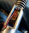
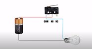
Dave Ps diagram was what I used and I actually found out removing the casing of the snap switch helped. I kind of want to glue a plastic piece to the bottom of the board and use that to depress the switch!
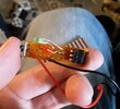
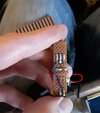
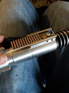
anyway, look at this mess - any tips are greatly appreciated. I broke it trying to stuff it in the box and have to re do the circuit.. I still have extra LEDs and switches
I realized the bulbs had to be at a right angle to the switches and that changes where the solder joints go... sort of.
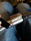
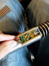
I swear it worked!!!’ Exactly like the scene... and then I broke it haha


Dave Ps diagram was what I used and I actually found out removing the casing of the snap switch helped. I kind of want to glue a plastic piece to the bottom of the board and use that to depress the switch!
anyway, look at this mess - any tips are greatly appreciated. I broke it trying to stuff it in the box and have to re do the circuit.. I still have extra LEDs and switches
I realized the bulbs had to be at a right angle to the switches and that changes where the solder joints go... sort of.
I swear it worked!!!’ Exactly like the scene... and then I broke it haha