Build Log - Fieldmarshall E11 Blaster

zjunlimited

Sr Member
Edit: All done. Photos added at the end of this thread. Thanks to everyone who posted their build logs for reference and for offering tips and suggestions on how to finish this kit. It was a thoroughly enjoyable build. Special thanks to Field Marshall for offering this kit.


=============
Thanks to Field Marshall for the Cyber Monday deal, I was able to pick up one of his E11 blaster kits recently. You can check this out and more from his website Blaster Factory.

This will be my second blaster build...my first being a Han Solo Denix DL44 (build thread here).

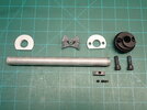
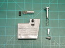
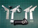
I'm just starting my research on the best way to assemble and to finish this. Additionally, I still need to pick up a mag and power cylinders at some point in the near future. For now, here's how the kit looks like once I was able to remove the abundance of bubble wrap and packaging that kept everything in pristine shape.

01 Kit.JPG
 
Last edited:
I have same kit, it is great! You will have a great time assembling it. I consider myself lucky, as I live in the same town as FieldMarshal and am able to go pick up my projects in person. He has an AWSOME operation going
 
I will call this the "getting to know you" phase. In short, this means...
  • a full breakdown of all parts
  • deburring edges / removing cast lines
  • giving everything a nice soapy wash down to remove all of the machine oil residue and debris
  • lubricate all threads
  • and of course all the while, familiarizing myself with how this is suppose to be assembled and keeping track of all of the parts (sooo many small parts and screws)
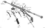
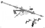
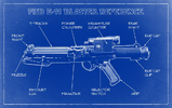
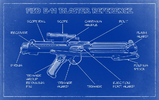
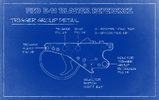
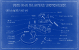
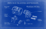
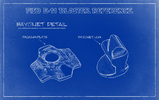
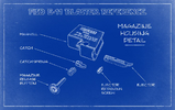
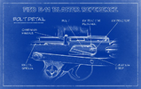
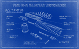
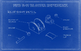
So that said, I "think" the diagram that Chris provided is quite clear and is a welcomed reference for these kit builds.

FM Diagram 1.jpgFM Diagram 2.jpg

However, there aren't any instructions for his replica hengstler and scope. Any ideas here?

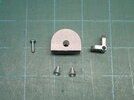
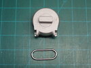
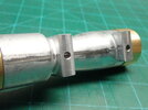
The scope seems pretty straight forward but there are 2 pins that looks to reside in two channels / holes between the screws. These appear to be decorative but I'm guessing they are installed with some adhesive? The tolerances aren't tight enough to be secured by press fit.

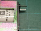
As for the hengstler, having never seen one of these counters before, I'm at a complete loss as to how to assemble at the moment....

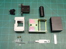
12 Hengstler Counter, replica 01.JPG
 
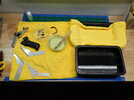
Well the research continues but in the meantime, I was able to finish washing everything down. Here's my wash setup...one tray to track all of the small parts, one with warm water with regular liquid dish soap with a brush to get into all of the small crevices, a clean water rinse basin, and a drying tray with a towel. Everything is then blown dry with compressed air.
20 Wash 01.JPG

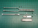
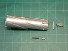
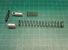
And here are all of the sub-assemblies for reference.
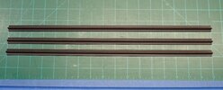
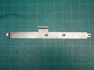
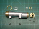
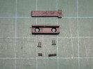
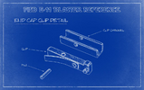
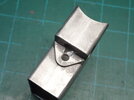
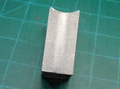
02 T-Tracks 01, uncut 17in each.JPG03 Muzzle and Rod 01.JPG04 Bayonet Lug 01.JPG05 Stock 01.JPG05 Stock Hinge 01.JPG06 Mag Well 01.JPG07 Grip 03.JPG08 Bolt 01.JPG09 Bolt Spring 01.JPG10 Scope Rail 01.JPG11 M38 Replica Scope 01.JPG12 Hengstler Counter, replica 01.JPG13 End Cap Clip 01.JPG16 Rear Sight 01.JPG17 End Cap 01.JPG

I'm sooo far from being ready to paint since there are many areas that I still need to clean up and fix (more on this later). But to get thinking on paint, from what I can gather so far it may be good to separate this into buckets....with the notion that everything in each bucket would be painted similarly but in reality it's not so simple. That said, here are some food for thought and for some brainstorming.

1) stock Sterling parts (exterior) - muzzle, front sight, receiver tube, bayonet lug, stock, stock hinge, mag well, rear sight, cap clip, cap
a) crinkle or hammered paint​

2) stock Sterling parts (interior)
a) barrel - flat black​
b) bolt, bolt assemblies - aluminum black with metallic silver on the ridge​
c) grip - does it really need a coat of gloss black or it a gloss clear over stock sufficient or maybe even no paint?​

3) all of the Star Wars / Stormtrooper conversion parts
a) scope - hammered on scope body, then brass paint on body, then flat or satin black overall​
b) scope rail - flat black​
c) hengstler counter - flat black​
d) power cylinders - flat black​

4) no paint
a) mag​
b) t-tracks​
 
Last edited:
REFERENCES

So after combing the web the past week or so, the following links are what I was able to find focusing on full FM builds primarily but also those that are metal builds or using FM parts. Note I found a number of resin and 3D printed E11 references but I did not include them here as they are not relevant.

General / Overview
FISD E-11 BLASTER REFERENCE
Fieldmarshall build by Fieldmarshall - where it all started (June 2016)
FIELDMARSHALL ALUMINUM E11 KIT by Fieldmarshall - assembly and finishing but updates abruptly stopped after a couple of weeks

Build Logs
My e11 build (Fieldmarshall kit) by Moussvroum - the only FM E11 build log I could find
Lucky#Eleven - Phoenix Props Pipe Kit with Completion Set, Conversion Counter, Inner Barrel and more Add-Ons - not a FM but a metal build
Just another E-11 build by tennantlim / Just another ANH E-11 blaster build by tennantlim - not a FM but some FM parts
Coloursergeant's Steel E-11 Blaster Build - demilled Sterling (w/crinkle paint) with some FM parts

Others / Specific Components
Installing the Stormtrooper Blaster T-Track
STERLING BLASTER CONVERSION - clearly focused on a vintage conversion (interesting read nonetheless) but helpful tips on T-Track install
E-11 STEEL PIPE BUILD - metal build, no FM parts but nice general tips and a fascinating read if you like build logs

Blueprint References from WA (first link above)
BP01.pngBP02.pngBP03.pngBP04.pngBP05.pngBP06.pngBP07.pngBP08.pngBP09.pngBP10.pngBP11.pngBP12.pngBP13.png

I hope this helps folks but if anyone can find links to other builds, I would appreciate it as well. Additionally, I'll add to this section as other links and references are found.
 
Last edited:
MagWell Prep

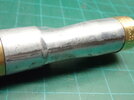
Pulled out my trusty files and dremel sanding bits and went to work on removing the cast lines and nubs. I also ran the files over all of the edges especially in the oval cut out section where the magazine catch will reside. There was a bit of slag and excess in that area but was easily corrected.

20 Mag Well 02.JPG

20 Mag Well 03.JPG20 Mag Well 04.JPG
 
Sight Guard Prep

I had two notable issues that I had to address with the guard....the overall "fitment" of the guard to the receiver and what I call the "overhang".

First up, the "fitment".

In this "before" photo, you can see the gap between the front guard and the receiver.
50 Sight Guard 01 Before.JPG


Simple enough fix. Using needle files I was able to remove some material on the guard to match the curvature of the receiver. Voila, done.
50 Sight Guard 02 After.JPG


Second, the "overhang".....and of course I didn't get a "before" picture :rolleyes: but a good portion (>50%) of the front of my guard essentially sat on the lip of the muzzle. This looked to be too far forward given some of the reference photos so I needed to bring the front edge of the guard aft to line up with the front edge of the receiver.

Applied some heat to the guard to minimize the potential of this part cracking or simply breaking.
50 Sight Guard 10.JPG


Next, using the handle of a medium size paint brush I pressed down and rolled it to the left in this photo. By doing this, I was able to "open up" the 180° bend of the guard just a tiny bit which also raised the front portion of the guard. I repeated this about 2-3x taking it slow and making small adjustments.
50 Sight Guard 11.JPG


Next, after heating up the guard again as previous, I used a flat piece of wood and pressed down on the front portion of the guard while positioning the wood handle in the bend to reduce the stress and any potential breakage or overbending. Again, 2-3x and small adjustments each time.
50 Sight Guard 13.JPG


Final result. Since I don't have a before photo, I would say the front section of the guard sat a bit more than half the thickness of the guard in front of the receiver's leading edge. You might be able to get a glimpse of this in the previous "fitment" photos above. So not a whole lot but I knew it was going to bug me and this isn't something you can easily come back later to address once everything is assembled and painted.
50 Sight Guard 03 After.JPG
 
Last edited:
Receiver / Stock Latch Cutout Prep

Ok so this next mod may be tough to explain so bear with me. Also, I'm using terms based on this reference so hopefully that will avoid any confusion.
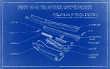
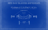
BP07.png


Once the stock is assembled and in the folded position, the "handle" would not sit flush with the "wishbone"...it would flop down and rattle around a bit. I would later find out the "catch" was not being fully extended and the culprit was that the cutout in the receiver was too short, limiting how much the "catch" could extend. So I break out my needle files again, squared up and extended the cutout length by removing roughly 2mm of material.

Again, apologies for the lack of a "before" photo but in the end, I'm left with 6mm of aluminum between the edge of the receiver and the edge of the catch cutout....and now, the "handle" sits perfectly flush with the "wishbone", rattle-free. :)
60 Stock Latch Cutout 02.JPG
 
With my vacation ending and work starting tomorrow, here’s the next part of the series where I go through the assembly of what I call the sub-components....grip, stock, bolt, and magwell. The hengstler, scope and power cylinders will come later which should wrap up the assembly of all sub-components.

I’m also now toying with the idea of strengthening the stock hinge like what Moussvroum did in his build so the bolts can be shortened. More on this later...

 
Hengstler Coil Fitment Prep

Now that assembly photos were posted by Fieldmarshall, I started working on the counter...please excuse me if I butcher the actual names of the various parts.

As you can see in the photos below, the coil was simply not fitting inside the frame and the screw holes were not in alignement.
41 Hengstler 01 Before.JPG
41 Hengstler 02 Before.JPG


In short, the plastic of the coil frame as well as the plastic insert were the culprits. I had to sand and trim away some significant plastic to make this all fit. For the coil, sand or trim the plastic until it is even with the coil itself....especially the backside (last photo).
41 Hengstler 03.JPG

41 Hengstler 05.JPG

41 Hengstler 04.JPG


The screw side of the insert itself needed some sanding as well as well as the sides. 250, 500, 1200 sandpaper was what I used.
41 Hengstler 06.JPG


I then had to round the corners of the insert as well.
41 Hengstler 08.JPG


Finally taking a file to ALL edges of the coil frame where it could be in contact with the plastic coil / insert, I was able to fully insert and seat the coil into the frame.

41 Hengstler 10 after.JPG
 
Hengstler Number Cylinder Prep

Next up was a welcome break from the coil and started work on the number cylinder. Simple and straight forward. As a side note, what numbers did others receive? I saw #001138 in FM instructions. Not sure if we were able to request certain numbers or if they were randomly sent out? in any case, moving along....

Starting with the ends of the cylinder, some slag needed to be cleaned up around the holes and the faces of both ends were sanded smooth (500, 1200 grit). This was needed to ensure the cylinder will fit true inside the frame during final assembly.
45 Hengstler 01.JPG45 Hengstler 02.JPG45 Hengstler 03.JPG45 Hengstler 04.JPG

The slight ridge on the frame where the leading "zero" of the cylinder sits required a bit of sanding for the cylinder to fit inside the frame. No biggie and 30sec with a needle file was all that was needed.
45 Hengstler 05.JPG


45 Hengstler 06.JPG


As shipped, there is some slag that will need to be cleaned out from the numbers.
44 Hengstler 01, numbers before.JPG


Some quick work using the picks primarily, they easily came out. Be careful with the utility knife. It will scratch the delrin (?) platic easily and I used it only to remove some stubborn pieces that would not detach using just the picks.
44 Hengstler 03, numbers after.JPG


Using the white crayon approach, rub the crayon over the letters in all directions to fill the voids. I would then dust off the excess, run my fingers over the numbers to tamp down / smooth things out (which would cause some of the crayon to flake). I repeated this (2-3x) until the voids were filled.
44 Hengstler 04.JPG


If you look closely, there are some "divots" left in the crayon that makes it look rough. I know this may be quite hard to see and once installed, no one will likely notice but as with all things, I noticed it and it bugged....lol.
44 Hengstler 05.JPG


Simple solution, blow some hot air over the numbers using a hair dryer and the gentle heat will melt the crayon bits just enough to smooth everything out. The remaining crayon reside on the cylinder was removed using a gentle massage from my fingernails and a slightly damp paper towel.
44 Hengstler 06.JPG
 

Your message may be considered spam for the following reasons:
If you wish to reply despite these issues, check the box below before replying.
Be aware that malicious compliance may result in more severe penalties.
Back
Top