The Electronics
OK, first things first: I don't know anything about electronics. If anyone can offer advice on how to do things better then it would be much appreciated for my next build!
So I had a look at the options for including an internal battery, switch and some sort of charging capability and I came up with the Adafruit micro-USB Lipo charger, a 3.7v 250mah rechargeable battery and a little toggle switch. It should be fairly simple but I actually blew up the first Adafruit board by accidentally shorting it with crocodile clips whilst testing...
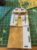
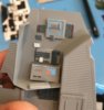
The front of the raptor has a panel that covers the join between the two haves of the hull, and behind this panel there's a big space inside so I decided to put the USB port and switch behind this panel, and then attach the panel on top with magnets.
I needed to cut out a few holes so I just snipped away with the Tamiya plastic cutters until I had a hole that a USB cable would fit through, and then I drilled one hole for the switch and one on the other side which would allow me to see the red/green charging lights on the charging board.
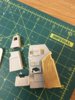
View media item 50502View media item 50503
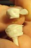
I used a SPDT switch (I think) as I couldn't find a small enough SPST one, so I just used two of the pins and it seems to work fine. I wired it into the -ve wire and then stuck everything in place with epoxy. Except it didn't stick for some reason, so I ripped it out and used superglue, which worked fine.
I gathered together all of the +ve wires from the spaghetti underneath the cabin and all of the -ve wires and began to solder them together (in two separate groups obviously!). I found the magnet wires to be most difficult to do, as I was very wary of damaging the wire whilst scraping off the enamel coating but got there in the end. I used a lot of heat shrink tubing, which I shrank down using the side of my soldering iron, as I don't have a heat gun, or the desire to buy yet another tool to take up space.
Some of the +ve have resistors on them (not all) as I understand most LEDs are rated only up to 3v as standard. The place I bought them from had 4.8v as the lowest option for pre-wired resistors so for the 0402 less I ordered them with resistors, and also some of my 3mm LEDs were from a different kit and already had resistors on them. I've no idea if resistors are a real necessity when there is only about .7v "excess" voltage, but I ran all of these in tests on a 4.5v source for a while and none blew up. I didn't put resistors on the 0603s because I can't solder that magnet wire very well. I thought soldering the legs of the resistors together would be easier than adding wires and then soldering them, but I was probably wrong about that - it wasn't very easy and didn't work that well. I did a bit of research and got some better tips for my soldering iron and some flux, which seems to help a bit sometimes with getting the solder to stick where you want it. Also someone bought me one of those "third hand" things with a light and crocodile clips to hold bits whilst soldering, which sometimes makes what was a seemingly impossible task only very tricky. For me at least.
View media item 50504
So eventually I got the wire spaghetti down to an acceptable volume that it would fit in the space.
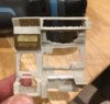
View media item 50505
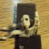
Neat and tidy? No. The brown tape is a fabric tape with zinc oxide adhesive which I used because normally it sticks to things really well for a long time (unlike duck tape which comes off after a while) and my electrical tape was just awful. Anyway, none of these worked. I should have bought some of those little plastic cable tidies with adhesive backs. Too late.
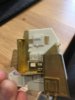
View media item 50503
So there it is with everything fitting in. I tested the charger and it seemed to work ok, and then I switched it all on and left it somewhere where it wouldn't burn the whole house down if it set on fire. Even with only 250mah running all of those LEDs it went for nearly an hour before the LEDs were too dim, which Is good enough for me. As mentioned before, I see this as a toy rather than a model for display (lucky as it isn't going to be display worthy!) and it will only be switched on for a few minutes at a time.
Now a bit later (about 2 minutes after I spent hours getting the hull pieces together, with much epoxy and superglue and filling and sanding and clamps and vises) I realised that I originally planned to light up the tips of the upper wings (front and back) like Lou Dalmaso has done with his. And then I watched his video and thought maybe I want to light up the lower wing tips too. Except that all the wiring is stuck in the hull and there’s no way I'm smashing it open to get to it. So I'm thinking about putting in another battery underneath the cabin floor (there is about enough space) and installing either four (or eight, if I do the lower wings too) red and green 0603 SMDs. They would be routed out the back underneath the engines and into the fins. The wires would be external for 10mm or so but I don't think it would look to awful as those magnet wires are really thin and if I glue them down it will just be another bit of detail. The only problem is I can't find blinking red or green 0603s. I think from watching BSG that the left side has red lights and the right side has green. I want them to be blinking like the strobes on modern aircraft i.e. on for a short time then off for a longer time, as I think it looks cooler than constantly on. If I do the lower wings the wires for those LEDs will need to be run externally for the last part as the "step" area of the wing is not hollow, and the SMDs would be surface mounted directly on the front and back sides of the step piece.
The other option is to use blinking 3mm LEDs which I can find, and run fibre optics. This would have the advantage of the LEDs of the same colour blinking simultaneously, but would mean there's no real way to do the lower wing ones as running fibre externally will look rubbish.
I also found an LED "flasher" chip which I could maybe use with the 0603 LEDs, but have yet to receive this to see if it works.
Let me know if anyone has any other ideas (other than "plan it properly next time")
")