1/350 E Lighting question

JerseyGuy

New Member
Hi all... new to the forums; longtime reader, but now I have a problem.... I'm working on my 1/350 TOS Enterprise and was testing the lighting kit. None of the LEDs seem to work. The strip lighting works, but no LEDs or the Bussard motors. I must be doing something wrong but I can't figure out what. My voltage tester confirms the boards and LED wires are getting power. I've plugged in the supplied transformer and spliced the wires together for the test.

Any help would be appreciated!
 
Hi JerseyGuy,

First off, welcome to the forums.

I'm sorry to hear about your troubleshooting difficulites. I haven't built the kit yet, but have lit a few models.

If your LED wires are getting power, but your LEDs aren't lighting there are a few possibilities...

-LEDs are shot (not very likely, but still possible)
-Wrong resistors have been used in the circuit (too high a resistance perhaps?)
-Reversed Polarity (Not likely as the motors would just reverse)
-Wrong voltage for that circuit, try looking at the potentiometer and meter it out.

Sorry I can't be of more help, but thank you very much for joining us here and we look forward to pictures!

Brandon
 
Hi Jersey Guy. I've done one of these kits. The instructions for stringing up the LEDs is confusing. Make sure you have the connectors on the right ends of the little LED sections. That will definitely cause trouble.

As for the motors, check all the wire connections at the plugs. I had a couple come loose or totally off. Also, be sure you are connecting into the correct circuit board.

Hope that helps.

Jon
 
As others have recommended...check the polarity of the LEDs. It does make a difference. I would add...check all of the wiring connections.
 
Thanks guys for the suggestions! When I have time in the next few days I may cut open the heat shrink on an LED to switch the wires and see if that makes any difference. A little disappointed Round 2 hasn't gotten back to me yet...
 
Extra points of clarification: LED's are light emitting diodes. Diodes are a 'one way' door for electricity, that is, the current can only flow one direction through them, so wiring them backwards means they can't light up. As for the resistors that Brandomack mentioned, each color of LED needs a certain minimum voltage to light up; the resistors modify the input voltage so that it enough to light them up but not enough to burn them out. A resistor with too high a resistance will drop the voltage too much and the LED won't be able to light up.
 
Thanks NextGenMaker - good words. Fortunately, tonight I solved my own problem. Now, remember I'm a novice at this....but when I went to test the lights, I just grabbed a random open wire to splice to the power supply (a "K" wire instead of a "J" wire!). Tonight I wired it up exactly as it will finally be, according to the directions (imagine that! Following directions!) and all tested fine! I'm very relieved and now the build can proceed! I can't imagine the letter of the wire made that much of a difference...

Thanks again everyone for the advice!
 
You're welcome, though I was just offering some context for the actual advice of brandomack and Jsimon999 which turned out to solve your problem.

Yeah, electrical engineering types are meticulous, because most components are delicate enough that you must be sure it works before it is ever made. Case in point: the TGA image format stores it's red, green, and blue color components for each pixel in the order BGR.

Why you ask? Why not in rainbow order, RGB? Well, the TGA format was created specifically for some of the first dedicated graphics hardware...by electrical engineers. So they, rationally, and at a time when there wasn't much precedent, ordered the components alphabetically.
 
Thanks all for your help! Things were slow going over the holidays with some travel for work and family visiting, but I was able to get to it.

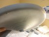
First, before all this, I spent a couple of weekends of puttying, sanding, priming, puttying, sanding, priming, etc., etc., those dreaded gridlines away...

Saucer.JPG Saucer & neck.JPG

And did my best to do away with the seam
Saucer edge.JPG

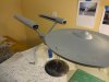
I even made an attempt at the bridge...
Bridge.JPG

I should say, although I've been building models since I was 5, I've never attempted one of this scale and complexity. I had several of the original AMT kits and sadly watched as the nacelles slowly dropped - if I was even able to get them on straight to begin with! I came across Steve Neill's build on YouTube and that inspired me to get back into it after many years away.

Anyhow, now that I'm happy with the saucer, I moved on to getting the Bussard Collectors right.
I went with someone else's suggestion of putting broken mirror pieces in, just like the original:
Bussard w mirror.JPG

I'm not so sure it makes a whole lot of difference...the original Christmas lights were more Omni-directional and so the mirrors would pick up more light from them. With the R2 lighting kit, the actual LEDs are buried under the plate that the "bulbs" plug into. I'm fairly happy with the result though:
DSC01763.JPG

My only issue now is that in trying to dull the outer domes, I sanded the first one, but thought that was too dull so I only sprayed Dullcoat in the other one which I thought came out about right. So, now I have uneven domes:
DSC01764.JPG

I hope that maybe I can buff out the sanded dome a little so that maybe only I will notice.

Thanks for reading!
 

Attachments

  • DSC01759.JPG
    DSC01759.JPG
    1.5 MB · Views: 161
Slow work over the weekend....small details and some preening. I spent far too much time pursuing what ended up being not worth it...an attempt to quiet the Bussard motors a bit with some foam and rubber:

Bad idea.JPG
In the end, it wasn't quiet enough to warrant the effort. Add to that, my plan was to extend the motor shaft with some brass tubing. Not owning a vise grip, there was just no way for me to cut brass and keep it perfectly straight. So, lesson learned.

I moved on to finish the lighting in the secondary hull - I ended up having to hot glue the LED strips on since their own adhesive kept popping off:
Engineering.JPG
I'm building it without the shuttle bay, as I'd rather have the bay doors closed, but then realized a lot of the lighting in the aft end relies on lights mounted on the shuttle bay structure. I suppose I could come up with another way to make it work, but it was just as easy to throw the shuttle bay together without worrying about painting it, and use it that way. That's next and then I think I'll be ready to close up the secondary hull. Every major sub assembly I glue together on this model seems to be a major emotional event. :eek

Today I worked on the nacelles. I figure I can glue the basic parts together and worry about tweaking the Bussards as the build goes on. I'm also waiting to install all the detail/darker gray accented parts until after the entire ship is together and painted its final color. I found it easier to glue the pylon into one side of the nacelle, so I could run the wire easier, and then glue the other nacelle half on:
Pylon.JPG

I'm happy with how it worked out:
1st nacelle.JPG

Probably won't get too much more done this week until the weekend. Next will be lighting around the shuttle bay, closing up the hull, and I've started experimenting with color mixes for the final color.
 
The kit is not for the faint at heart, JerseyGuy. It's a real challenge even for the very experienced I found. I had a lot of trouble getting the shuttle bay assemblies to fit in there. I wound up completely customizing the whole thing inside and closing it up. I'm not sure how other got it all to work but I gave up.

I too tried to quiet the motors on my 2nd build but didn't see any difference in padding it up. I did add some cotton balls down the length of the tubes and I think that produced some sound and vibration associated noise muffling.

Just keep taking your time. It will come out great eventually.

Jon
 
Thanks for the words of encouragement, Jon! I've tried to approach this project with a view that I don't particularly care when it gets done (different from a lot of my past projects...) just that it gets done. It will, and I've already learned a lot along the way.

Dave
 
if the "sanded" bussard cap is the one where the black lines are less defined, I think that looks more
like the filming model.
 
Yes, the more faded one is the "sanded" bussard dome. I agree, it does look a bit more authentic, but in person the lights are fairly dim coming though it. If I had it to do over again, I might get a Tenacontrols PCB and forgo the spinning "blades". The plastic "bulbs in the R2 kit just don't transmit enough light from the LEDs for my taste.
 
Last edited:
So, I got less work done than I thought - both the wife and I were hit with bit of a stomach virus, which has somehow missed our 2-year old. Usually he's the one bringing illness into the house!

I was able to get some more preening done on the nacelles
DSC01801.JPG

And then I continued on with the shuttlebay/light holder...I ended up trenching out a little more on the top, towards the rear and into the control room over the bay doors:
DSC01803.JPGDSC01805.JPG
Looks pretty bad, but no one will ever see it. There was just no way that flat LED and wire were going to make it through the tiny space. Now everything fits rather snug, but a test fit of the shuttle bay and engineering hull revealed everything goes together fairly nicely. There's going to be about 1/32" gap towards the rear of the ship, but from what I've seen on the forums, that seems to be about par for the course. Not like it doesn't already have a couple of pounds of putty on it....

The test fit revealed that I needed to slice away just a bit of this part:
DSC01804.JPG
Not quite sure what you call that, but it seems like they intended to have a connection there, until the lighting kit came along. That's right where the LED for the fantail rests under the shuttlebay, and some of the initial trouble I had closing up the hull was because that was pressing against the LED.

So, that's all I got done. I found myself sitting there tonight thinking I'm probably ready to seal up the engineering hull, so I thought it best to walk away for the night, get some rest and let the cold medicine work. There's still plenty left to do, but I find I don't want to finish, I'm enjoying myself so much!
 
Last edited:
Argh! I don't know what the problem could be...I click the "Insert Image" icon just like I did on my other posts. I've deleted and tried reposting 2x now. Pictures are the same size and format, stored in the same folder as my other pictures. Hmmmm........

Well, I'm at a standstill until this weekend anyway - while test fitting the shuttlebay, engineering hull and nacelle pylons last night, somehow I managed to break one of the wires leading to the port ion pod. Not a big deal, but I need to get to a real hobby shop to get some more shrink tubing - Hobby Lobby won't have that. It's about a 40 minute drive for me to south St. Louis to get a decent hobby shop. I've been meaning to do that anyway as the tubing that came with the lighting kit is too big and doesn't shrink tight against the small wires.

Once I get that done I should be ready to close up the engineering hull and attach the nacelles and saucer.
 
Well, I was able to make some decent progress in just a few hours this afternoon...

I got out to the LHS and got some decent shrink tubing and was able to fix my inadvertent break:
DSC01810.JPG

Engineering hull and warp pylons/nacelles ready for assembly:
DSC01811.JPG

And I took a deep breath and dove in:
DSC01812.JPG

There's a small gap at the rear, as expected...
DSC01813.JPG DSC01814.JPG

Nothing some putty won't take care of! While that sat for a couple hours, I preened the saucer a bit more, and mixed up a color I'm pretty happy with...looking forward to seeing how it goes on though. Before coming back out of my cave, I couldn't resist attaching the nacelles too:
DSC01818.JPG

I'll let that simmer for about 6 hours or so, but before I go to bed I'm sure I won't be able to resist attaching the saucer/neck assembly. That's it for now! Hope these picture post....

Dave
 
Hello all... been a slow week of preening. Putty...sand...prime...repeat.... But I'm quite happy with how things are turning out:

DSC01821.JPG

I feel pretty successful at filling the gap at the rear of the engineering hull:
DSC01828.JPG
This is about 90% there...I haven't done the final sanding after the last primer coat but I think it should come out pretty well.

I'm particularly proud of the underside, of all things:
DSC01826.JPG
That's mostly putty there under the shuttlebay. There was just a little lip from the way the fantail fit that needed to be blended in with the underside, and I have to say, it came out rather well.

One thing I wish I knew more about beforehand was the preening required around the shuttlebay itself. I haven't seen much discussion on it, so maybe its just me, but I had a dickens of a time getting in there to putty after it was installed. And then sanding was just a whole new level of pain, but after about 3 days just spent on that......well...its almost there:
DSC01824.JPG

All in all I'm quite happy with how its going. I'm going to be getting to a standstill though.....once all the puttying and sanding is done, I'll be ready to apply the final color to her. But I don't particularly want to asphyxiate myself in our little craft room, so I'll need to be up in the garage. However we're not expecting temps much above freezing here in the St. Louis area for the forseeable future.
 

Attachments

  • DSC01830.JPG
    DSC01830.JPG
    1.5 MB · Views: 141
Last edited:
Back
Top