SS AT-AT armature

Hi Wayne, I wish this is what was happening because it would be a lot cooler.
I came to my own conclusion that the swivel plates on the knee were rotated by hand. Some of them swing so wildly and fast (and not in sync) with a slower velocity on the reverse swing, that I figured there had to be a human element in that. Dissecting the armature has shown there's really not much happening behind these knee parts. There is something interesting though below the knee that's not often seen...


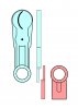
View attachment 302558

A milled hole, with electrical wires nestled under a washer in the knee (which acts as a spacer) that terminate at the screw which holds the swivel plate (and part it sits on) to the other/inner side of the knee.

I think this is only cosmetic, and serves no other purpose other than to look like there's hydraulic hoses or something being fed to the knee or upper leg.


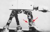
That's very interesting. I've noticed that too. Here's another observation. In this first photo, there are wires or cables coming out from the piston area. Could this be connected to the knee in some way? I don't know about you, but it sort of looks like everything is operated by cables and pulleys, despite what's been written in articles. Why would they have a round indent (in the upper leg), with a spindle and indented tracks for the pistons?

To me, when I saw the AT-AT for the first time, I automatically thought of cables and pulleys. :confused
 

Attachments

  • Knee Wire 02.jpg
    Knee Wire 02.jpg
    729.4 KB · Views: 457
  • Knee Wire 01.jpg
    Knee Wire 01.jpg
    363.9 KB · Views: 340
I'm sure there weren't any cables and pulleys linking parts together. That would take away the ability to animate specific movements to camera. The animators need to be able to adjust each moving part separately. If two or more parts are linked, then they don't have that freedom. More likely those are electrical wires to light up the cockpit or trigger smoke bombs and squibs.

You guys are doing some amazing work here!
 
Yeah there weren't any cables and pulleys. However several parts were linked together to not have to animate them separately. When you move the upper leg, the pistons moves and the rectangular hub as well as the break pad. As far as I know all the inner mechanism have been removed a long time ago from the 3 screen used AT-AT's and the parts move now freely.
While the idea was good, it proved to be not very reliable and it shows in the movie, in several sequences, pistons are stuck :p

I too think like Matt said that the knee pads were animated by hand though.
 
Hey Everyone,

It's been some time. While scrutinizing the knee joints, I've noticed that the upper leg knee joint is on the inside and lower leg joint is on the outside. Can anyone confirm this?

Here's a few pics to illustrate.
 

Attachments

  • Knee Hinge 00.jpg
    Knee Hinge 00.jpg
    496.2 KB · Views: 355
  • Knee Hinge 01.jpg
    Knee Hinge 01.jpg
    869.8 KB · Views: 403
  • Knee Hinge 02.jpg
    Knee Hinge 02.jpg
    169.8 KB · Views: 374
Definitely correct but something that probably wasn't unknown before now. I've seen images of the legs in parts on the table that show this. However, I did realise two things which I personally didn't know beofre today. That is there is a slot on the knee joint between the upper and lower legs.....

057_SWI_0966a.jpg

..and the 3 strips down the sides of each leg are actually two U beams, probably Plastruct.
056_SWI_0965a.jpg
 
Definitely correct but something that probably wasn't unknown before now. I've seen images of the legs in parts on the table that show this. However, I did realise two things which I personally didn't know beofre today. That is there is a slot on the knee joint between the upper and lower legs.....

View attachment 323812

..and the 3 strips down the sides of each leg are actually two U beams, probably Plastruct.
View attachment 323813


Yes, I noticed that too. I didn't include that in my inquire, fearing it might confuse the 'knee' question. Good observations. As for the U beams, I think you're right. They look more like detailing than being part of the original armature.
 
I just found this picture of the Walker Fleet posed together during Empire. Not sure if this is all of them, but I count at least seven!
ESB_HothWalkerFleetInShop1.jpeg
 
I think some are prototypes and some are screen used. You can tell by the hip plates. The prototypes have the double slots along the lengths and the screen used have the single angled slot.
 
These pics any help to you guys? Not sure where I got it but I saved it because it showed an angle I had never seen before. I know they are crappy but I remember I couldn't save the pic so I had to take screen pics. I took a bunch of the different areas as I had plans of doing this project one day. If they are useless, ignore me. lol
DSC01510.JPG
DSC01511.JPG
DSC01512.JPG
DSC01513.JPG
DSC01515.JPG
DSC01516.JPG
DSC01518.JPG

Also got this one.
761vl.jpg

If you need the full size pics let me know I can send them to you.
 
This thread is more than 5 years old.

Your message may be considered spam for the following reasons:

  1. This thread hasn't been active in some time. A new post in this thread might not contribute constructively to this discussion after so long.
If you wish to reply despite these issues, check the box below before replying.
Be aware that malicious compliance may result in more severe penalties.
Back
Top