Vader MPP bubble mounting

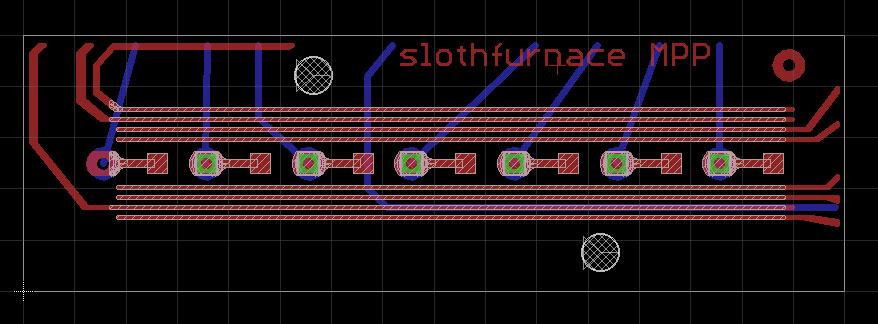
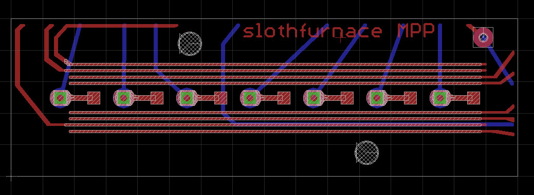
I just have a question. What are the green squares on the rendering, the mask surface? Should they be moved down onto the squares and not on the "loops"?

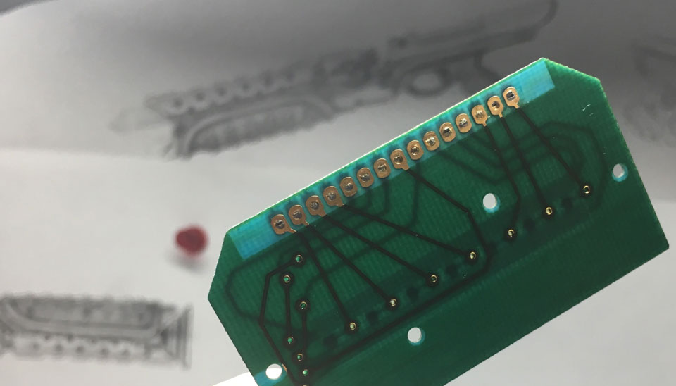
I personally believe the pcb was blue, but am fine with green. I would pick up two either way.

The green squares are the representations of the VIA through-holes. They will be merged with the gold plated traces in the final product. They are just there to show the manufacturer where to drill all the way through the board, and fill that hole with metal.
 
My initial instinct was that the board was green, but upon closer inspection, I believe that the board is blue. I vote for blue and as large as a bubble strip.
 
I'll definitely take 1, blue, matte.


Are you working on the ROTJ Skywalker circuit card on blue as well?
 
When the bubblestrip and board used for the ESB/ROTJ MPP came from an Exactra 20 ... this should be the colour of your replica board :


... taken in a Pro-studio and lights and color corrected with a greyscale ... so at least definately more green than blue, Slothfurnace :)

When a TI-2000 was used instead the colour is more turquoise ... a mix between blue and green as seen here :


Chaïm
 
This is the color green they offer, though I have not seen it in matte finish yet...

AN_Board_FirstBuild.jpg


I also have not seen the blue they offer.

We're going to get close to this, folks, but upon inspection of the board sent to me. It seems to be a blue tinted board, with green semigloss soldermask applied over the blue substrate...

boardcolor_01.jpg


I believe matte finish would be a mistake, as this board I have does have a gloss to it, but the green soldermask is mottled.

I'd say green or blue soldermask, normal gloss. Matte is REALLY matte. I think it will be closer if we don't do matte. Just my opinion.
 
After looking at all the photos im going to have to say the card looks like mossy green.
Both sets of photos (from the movie museum and prop shop) suggest green to me.

In the museum photo you can compare the color to the ROTJ poster in the background.
The poster is clearly blue and yet the card looks greener.

Theres also the photo that shows where the card was cut down...the exposed cross section looks pretty green to me.

Thats just my opinion.
 
Ok, final design time!

mpp_card_04.jpg


The white hashmark sections represent the soldermask stop. So those parts exposed will be gold plated. Soldermask will cover the rest of the board. Note that on my reference board provided by teecrooz, the gold plated traces extend under the soldermask a bit to the rightmost and leftmost traces on the board, so that is what I replicated here.

I also edited the spacing on the hole-pads relative to the square pads on the middle to be more accurate, and edited the S curve coming down off the right side of the hole pad, and flowing down to the long trace headed right towards the square LED pad.

All this is down to a fraction of a fraction of an inch, but it's important to me. I believe this is the most accurate representation of the circuit layout I can make at this time.

So far, I am leaning towards a standard green board/soldermask with gold plated leads exposed in the center of the board, and running under the green soldermask.

If, in the future, we want blue, we can chat about that, but it seems like green so far is where this is leaning.
 
Would it be possible for all the gold trace to be available? Posts 27 and 36 show this. I only ask because of how we need to cut the bubbles/board (post 5) the far left oval will show under a bubble, but will not be gold.
 
Would it be possible for all the gold trace to be available? Posts 27 and 36 show this. I only ask because of how we need to cut the bubbles/board (post 5) the far left oval will show under a bubble, but will not be gold.


Yes, we could, but let me ask this:

Since the photo you mention in post #5 has only five bubbles/hole tabs, and I am recreating the entire board with seven bubbles/hole tabs, would it not be true that you could section off the board however you see fit, and include the one gold arc section of hole tab?

Check my logic on that, I do believe we have that covered.

Unless we all want gold plated traces with no soldermask, which I could do, and would be cheaper, but I'd like to nail the majority of people's desires on this to begin with, then address any further demand once we get the first batch in.

Or, yeah, I could just not cover that last oval with soldermask.
 
I only know that the cutting configuration in post 5 works. Patrice cut the other way in the first post, but I have not tried that one myself.
 
How about I just keep the soldermask from printing on that last oval? Easy enough to do...

mpp_card_05.jpg


I mean, it' won't be super accurate to what I have here, but it might afford people more options to cut it the way they want... I'd be fine with that.

I also didn't like the fact that this layout didn't have the traces and hole going to that one spot in the top right corner, so I added that. It'll all be cut away, but I'm nitpicky like that.
 
Looks fantastic what comes out. Great job guys and thanks Brad for producing them.
Even if it seems not the original color, blue looks better to me and make it more exclusive.

Envoyé de mon PLK-L01 en utilisant Tapatalk
 
To me it looks like the hardest part in reproducing these would be to find a PCB manufacturing house that could provide the card in the right colour and with a very thin blue solder mask like the original. I have not seen any modern board that comes close to the one in the Exactra.

I have been thinking that if I were to make these, I think I would ignore those who would want one for a Luke ANH - make them the right size for an MPP to begin with and skip the green solder mask over the blue. Instead use black solder mask and white screen printing to create mock LEDs.
Then after I got the boards, I could dye them blue-green in a dye-bath or with a marker pen.
I am not sure that there really is solder mask in-between the gold traces under the bubbles. If not, then that would leave only a couple traces at one end that should be covered with solder mask instead of gold.

The nature of the Vader board has holes through it all down the middle. That would put holes on the other side, as well. I'm also recreating the backside of the MPP board, so if I were to do a blue version of the ROTJ Hero, it would need to be a new board layout.
Not to mention that the Luke ROTJ board is also wider (18mm vs 16mm) and thicker (1 - 1.2 mm vs 0.7 mm)
 
Last edited:
How about I just keep the soldermask from printing on that last oval? Easy enough to do...

http://www.slothfurnace.com/images/clampcard/mpp_card_05.jpg


I mean, it' won't be super accurate to what I have here, but it might afford people more options to cut it the way they want... I'd be fine with that.

I also didn't like the fact that this layout didn't have the traces and hole going to that one spot in the top right corner, so I added that. It'll all be cut away, but I'm nitpicky like that.

So this will be mounted behind a bubble strip, or are you making the bubble strips as well?


Sent from my iPhone using Tapatalk
 
This thread is more than 3 years old.

Your message may be considered spam for the following reasons:

  1. This thread hasn't been active in some time. A new post in this thread might not contribute constructively to this discussion after so long.
If you wish to reply despite these issues, check the box below before replying.
Be aware that malicious compliance may result in more severe penalties.
Back
Top