You are using an out of date browser. It may not display this or other websites correctly.
You should upgrade or use an alternative browser.
You should upgrade or use an alternative browser.
Y Wing based on the Dave G open source project
- Thread starter Scott Graham
- Start date
MonsieurTox
Master Member
Found the Red part while I was looking for something else. It was a turret from a battleship. Cant remember which kit but Im sure I van find it again. Probably airfix
MonsieurTox
Master Member
Found it again, Airfix Scharnhorst
- - - Updated - - -
I saw the yellow part on another Y, cant remember If it was the MoM or Gold leader
- - - Updated - - -
I saw the yellow part on another Y, cant remember If it was the MoM or Gold leader
Wow Julien! Thanks. I love when things like that happen. It definitely looks like a ship part.
The yellow part looks familiar to me too. Like a large part from a large kit. Almost like a jack part of a tank.
- - - Updated - - -
Ok. Two down...
The yellow part looks familiar to me too. Like a large part from a large kit. Almost like a jack part of a tank.
- - - Updated - - -
Ok. Two down...
Attachments
Julien: I've noticed there's also a 1/400 Scharnhorst by Airfix. Are you referring to 1/600 or 1/400? Thanks in advance.
MonsieurTox
Master Member
It's 1/600, this kit is a donor of the original Y body casting.
Thanks. It's time to sell off the 1/400 that just arrived then...")
None of it looked like the piece. What was most like it was too big.
None of it looked like the piece. What was most like it was too big.
MonsieurTox
Master Member
Don't think Airfix ever produced a 1/400 naval ship. 1/400 is the scale used by Heller for their naval ships, 1/600 is the scale used by Airfix. At some points Airfix reboxed Heller kits and Heller reboxed Airfix kits. What you got is actually a Heller Scharnhorst, not Airfix
Ah, ok. It really looks inside the box like a Heller. That makes sense.
Just a note on the droid socket... it was intended that an overlay of styrene be added with a smaller more fitting hole for the droid. When you look at some of the reference photos you can see that there is a thin sheet and the underneath it's more open. I think in the original castings it was just a rectangular recess and the overlay was added. It's one of the things I hope to add to my 3D model in time. Scott also gave me some notes on updates to the neck geometry. Again, I hope to get to revising the files in time, but I'm swamped with the fuselage castings at the moment.
I hope that everyone keeps in mind that the files are of a work-in-progress design (not a finished model) and are sure to get revised by me (and hopefully others) as we start putting models together and discover what works and what doesn't.
I hope that everyone keeps in mind that the files are of a work-in-progress design (not a finished model) and are sure to get revised by me (and hopefully others) as we start putting models together and discover what works and what doesn't.

Hammer3246
Sr Member
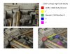
I'm pretty sure they're all from the Tamiya 1/35 25pdr. There's 3 separate parts.Also, would you be willing to share where these 2 kit parts circled in your image are from? Thanks in advance.
View attachment 662295
Last edited:
I've gone to v3 on the files but I can't get the area correct where the morgan part fits on the neck. There's too much surface manipulation needed. I'll try to update with some pics on my v3 parts soon.
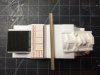
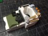
Here are the v3 parts. I've adjusted measurements about 1-2mm for each part. All parts are just put in place - not cemented yet.
I raised the front neck piece a couple of mm so the m577 piece sits at a good height against the droid socket.
The droid socket was widened a little so the jack piece and m577 pieces could sit beside the droid. You'll notice that the shell welder hexagonal piece barely fits. It's also placed kind of sloppily by me. The parts that sit behind the droid socket are sitting on a solid rectangular 3d printed bar. I added that because I didn't know how to manipulate the files well enough, but I could make an extra, solid piece they could sit on.
Overall, the top area works now. Not so with the bottom piece.
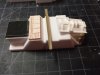
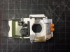
The bottom piece I widened so it would match up with the widened droid socket piece. So now it's too wide for the m577 vent and rectangular sealab parts. I had to also widen the slot where it sits on the aluminum armature, also because I couldn't manipulate the exterior surfaces separately.
The morgan part is also too wide for that part. It needs a channel to sit in, and that quad/25 pounder part at the sides of the morgan piece still won't fit well.
So that's the story: upper areas are ok, while widening the bottom piece didn't work out so well. It was pretty spot on in the first place. So there's a mismatch, potentially, between the upper and lower pieces. I don't know how that would be fixed as of now.
I also couldn't work on the wedge pieces that go on the bottom because they contain diagonal surfaces that I don't know how to manipulate in rhino. Dave can probably figure out all of this quicker. It's probably worth waiting for his mods.
I raised the front neck piece a couple of mm so the m577 piece sits at a good height against the droid socket.
The droid socket was widened a little so the jack piece and m577 pieces could sit beside the droid. You'll notice that the shell welder hexagonal piece barely fits. It's also placed kind of sloppily by me. The parts that sit behind the droid socket are sitting on a solid rectangular 3d printed bar. I added that because I didn't know how to manipulate the files well enough, but I could make an extra, solid piece they could sit on.
Overall, the top area works now. Not so with the bottom piece.
The bottom piece I widened so it would match up with the widened droid socket piece. So now it's too wide for the m577 vent and rectangular sealab parts. I had to also widen the slot where it sits on the aluminum armature, also because I couldn't manipulate the exterior surfaces separately.
The morgan part is also too wide for that part. It needs a channel to sit in, and that quad/25 pounder part at the sides of the morgan piece still won't fit well.
So that's the story: upper areas are ok, while widening the bottom piece didn't work out so well. It was pretty spot on in the first place. So there's a mismatch, potentially, between the upper and lower pieces. I don't know how that would be fixed as of now.
I also couldn't work on the wedge pieces that go on the bottom because they contain diagonal surfaces that I don't know how to manipulate in rhino. Dave can probably figure out all of this quicker. It's probably worth waiting for his mods.
Attachments
Hammer3246
Sr Member
I think the bottom piece has a taper as opposed to the top and the morgan should sit flat rather than the drop on the back half of where it sits, this would give more room for the 25pdr, but the whole neck needs to be longer too. Modifying it would probably screw with the armature but I'm sure it would be easy enough to add to it.
Thanks for the update Scott. So did you have to lower the very rear of the the top of the neck where the orange/tube looking pieces (sorry don't know the part) meet up with the main fuselage? The reason being, I notice the top of the rear of the neck sits flush with the main fuselage on Dave's design and I'm pretty sure that crevice with the orange part should sit below the main fuselage.
Big Dog
Active Member
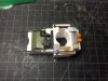
Looking at the underside of the neck, I think the width for the morgan piece may be correct or very very close. The morgan piece seems to be trimmed actually. Those flat edges it has on the long sides are not present if you look at the map of the underside neck. Check this image below and notice how the circles on the morgan piece are trimmed flat on one side.

I agree that the lowered middle half of the neck needs to be raised flat with the half closer to the McDonnell phantom piece. And a raised section needs to be made for the matilda and round sealab piece. This can be seen here:

I'm thinking of getting a Rhino license since it's not too expensive while I'm still a college student but I don't have much time these days to learn it.
Edit: Oh and which sealab piece is that you're using near the R2 strip? I can't seem to tell from looking at a scan as to which piece it is. Have you modified some edges to it? Thanks for printing out that section and testing it out to see what works and what doesn't. Great work Scott!
I agree that the lowered middle half of the neck needs to be raised flat with the half closer to the McDonnell phantom piece. And a raised section needs to be made for the matilda and round sealab piece. This can be seen here:
I'm thinking of getting a Rhino license since it's not too expensive while I'm still a college student but I don't have much time these days to learn it.
Edit: Oh and which sealab piece is that you're using near the R2 strip? I can't seem to tell from looking at a scan as to which piece it is. Have you modified some edges to it? Thanks for printing out that section and testing it out to see what works and what doesn't. Great work Scott!
Similar threads
- Replies
- 2
- Views
- 464
- Replies
- 3
- Views
- 636
- Replies
- 18
- Views
- 2,534