mung
Sr Member
About a year ago I picked up a Heller Super Frelon 1/35 scale helicopter kit for half price from my local hobby shop
which has since closed down.
I thought there may be some useful kit parts for detailing inside the box, and there were but the quite large hull also
presented some possibilities for some future kit bashing spaceship action.
The future is now, inspiration suddenly struck (if inspiration strikes run with it I say) and true to form I started another
project without finishing the numerous projects already on the go.

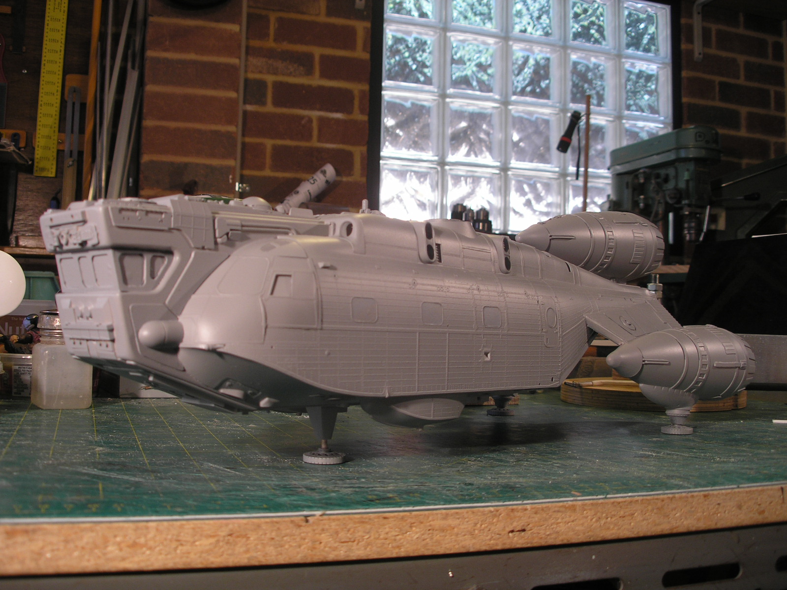
I followed my usual trick of separating the two halves of the fuselage by adding 2mm styrene in between, making
a wider form.
Bulkheads were added and an attempt was made to keep it all square.
Unfortunately the fuselage moldings exhibit some warpage and a slight twist crept in once the solvent had set.
Not so too many people would notice this and these things do happen even when being diligent.


I rummaged through my box of plastic shapes and dug out three acrylic wineglasses purchased from a charity
shop which would make good engines.
The bases were cut off and the stems rounded of on the disc sander and finished with wet and dry sandpaper and water.

In the same way as previous projects, I heated and formed some 2mm styrene over a wooden former to make
a strong engine mount panel for the two side engines.
A wooden jig was made up to glue the engine cups at the right angle and position.
Some extra strips of scrap styrene were added to increase the area of the glue joint.
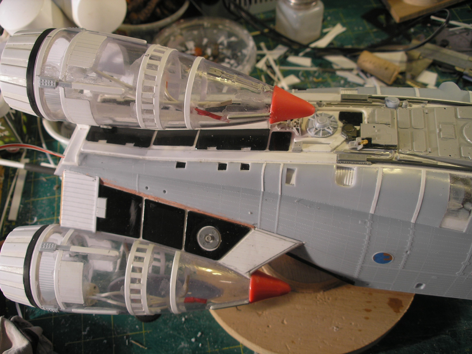
This whole assembly then gets glued to the under side of the tail of the fuselage and another styrene panel gets
added between the engine and the tail to thicken the "wing" mount.


Below you can see the test placement of the engines.


I had a look around my local hardware store for some useful shape I could use for engine nozzles but couldn't
find anything suitable so I decided to fabricate something.
I turned a conical ring on the lathe from a piece of a pvc pipe joiner.
The rings had a slight rebate machined on the back edge so they are a push fit into the back of the engine cups.
I super glued a strip of ribbed evergreen plastic sheet to the inner surface and then made a jig to glue some evergreen
strips to the outer surface.
The strips are located at the correct height by a chunk of styrene and the jig is marked around the circumference
in even divisions.
As each strip is superglued, the ring, which has a small mark at its base, is rotated to the next marking and the next strip
glued and so on.


Once all the vertical strips are placed, a strip of 1mm styrene is glued up against the end of the strips around the ring.
The picture below shows the three steps. Note that the strips are slightly oversize and are then sanded flush and rounded off to finish.

Again following my usual practice I employed LED downlights and ceramic connectors for the engine lights.
A rebate was also machined into the back of the nozzles to seat the downlight bulbs.
These are a bit of a loose fit so I am planning to secure them with a few spots of superglue.
I don't envisage ever having to replace them as they have fairly long lifespans and will barely ever be turned on,
but they can always be cracked out if desired at some stage.


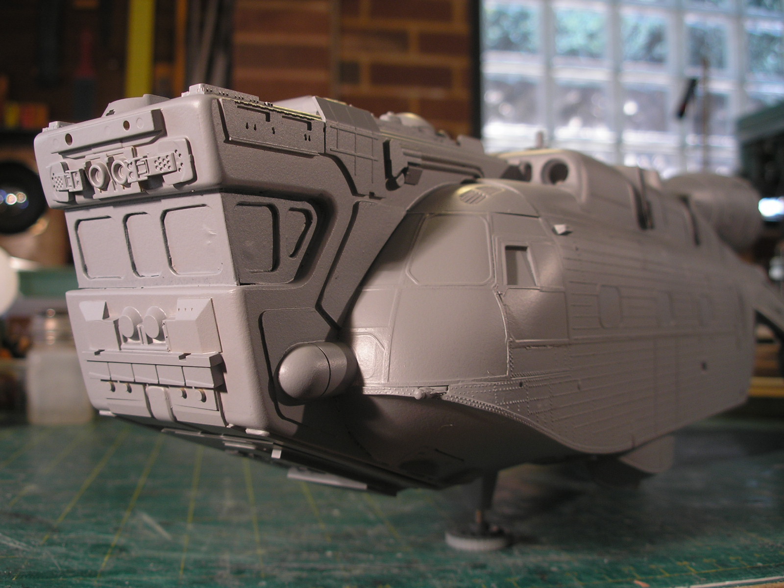
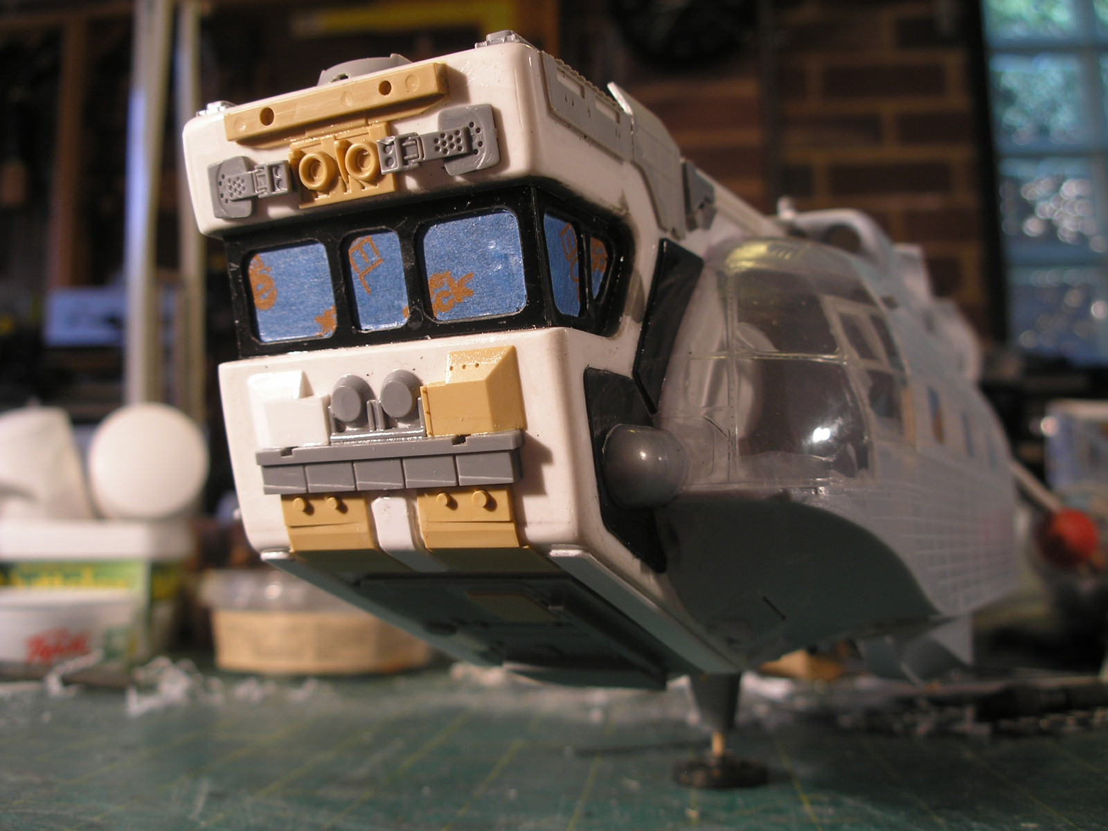
A cockpit section was built from 2mm styrene.
The kit pilots and some of the cockpit parts were employed along with some other random kit parts and some
red led interior lighting.
The two 2volt leds had a suitable resister added in series to allow for the 12volt power supply.
Here you can see the cockpit insert with white primer applied.


Below is the cockpit LEDS and resistor mounted from the top.
This will be covered with some detail paneling.
The cockpit has to have clear thin perspex windscreen panels added and the interior painted before finally sealing
it up when it is glued to the rest of the hull.


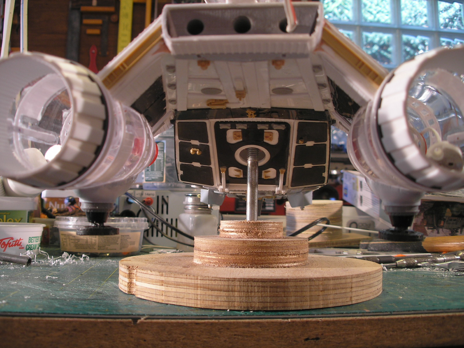
Down the back end you can see one of those 3/8 whitworth threaded furniture leg mounts I use as a solid mounting
point from the top and the bottom.
It is screwed to some plywood which is super-glued into the hull. I still have to get hold of some DC power connectors
to install to provide the power.

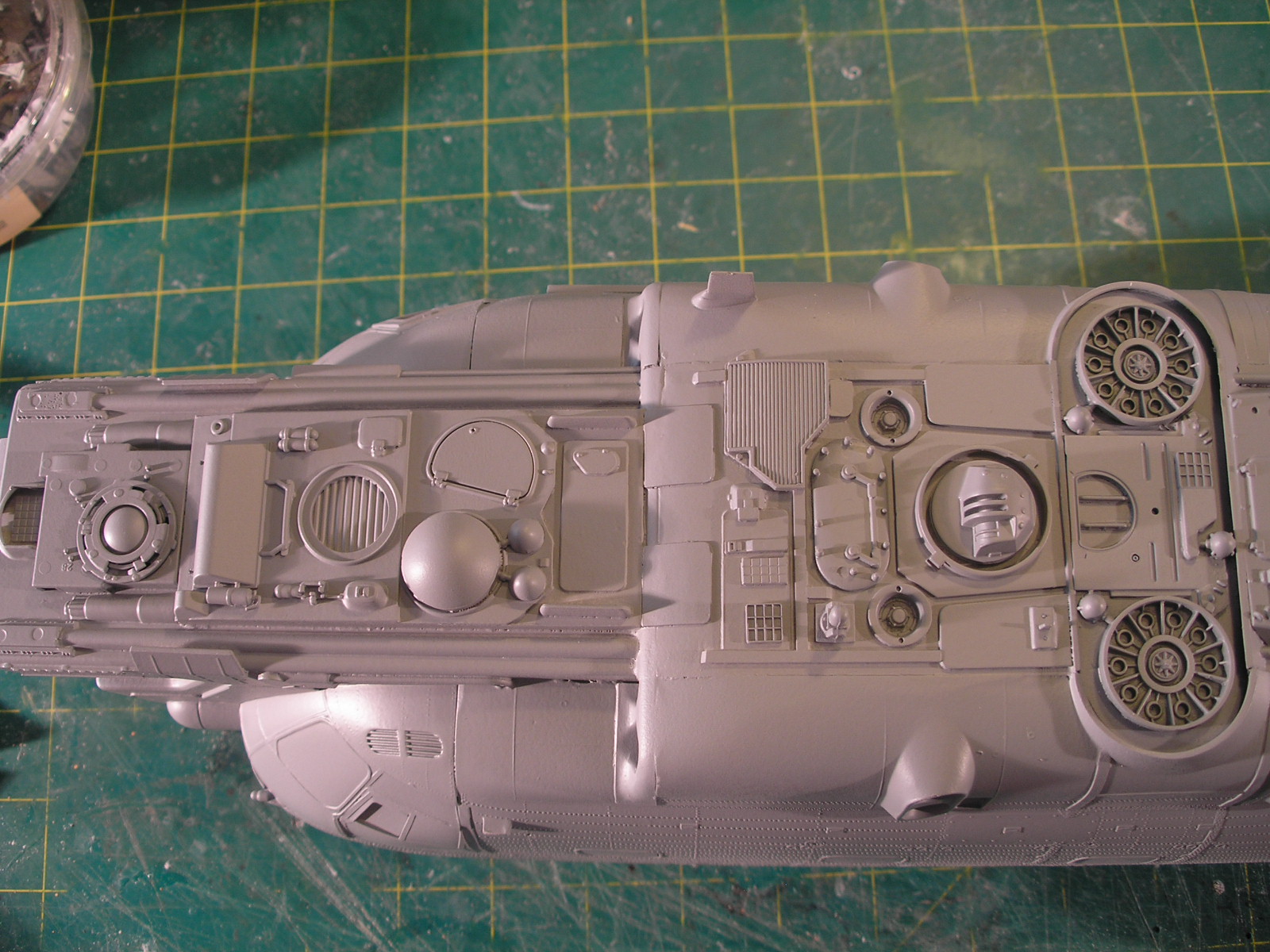
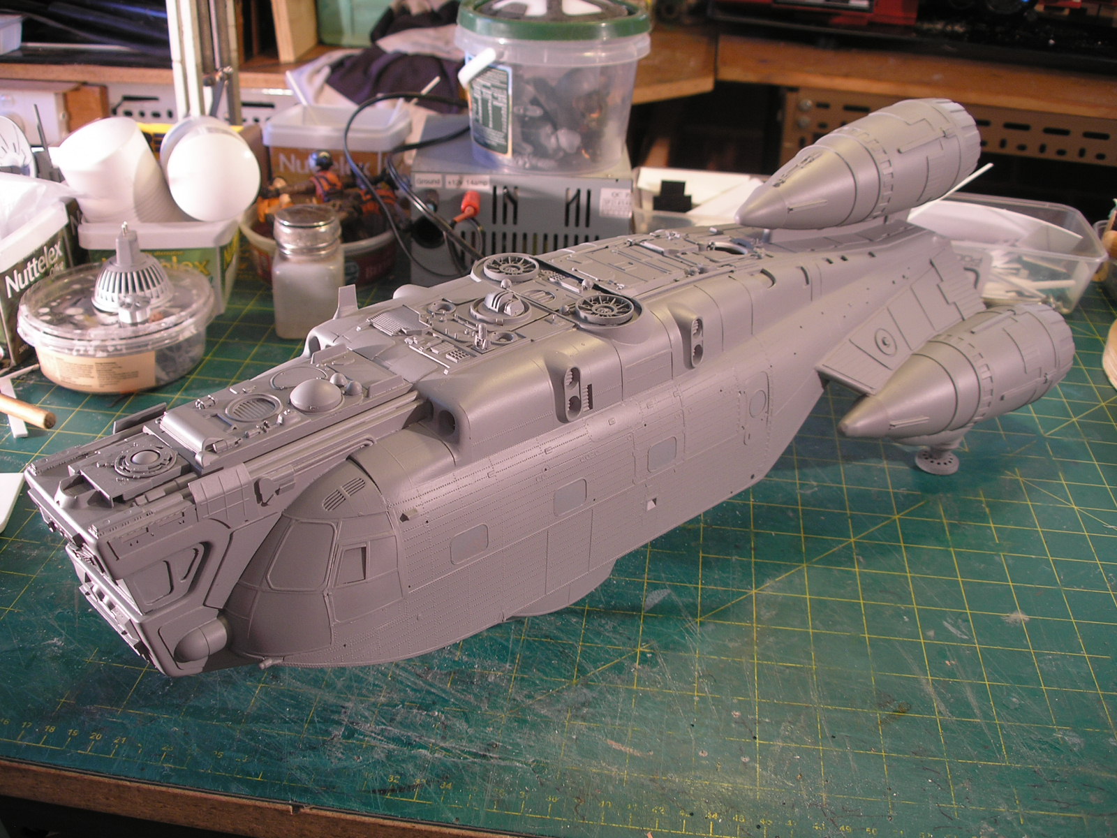
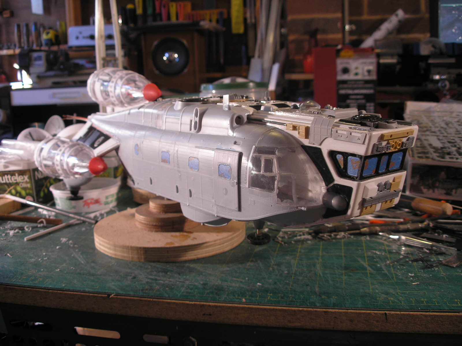
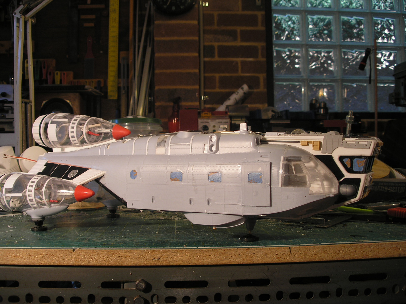
Here is the project so far with the engines mounted and some detailing ( my favourite bit) started on the top.
I always make use of any openings that exist in the kit and make them part of the detail design.
I usually back holes with some ribbed evergreen to make vents and ports of some kind.


More soon...
which has since closed down.
I thought there may be some useful kit parts for detailing inside the box, and there were but the quite large hull also
presented some possibilities for some future kit bashing spaceship action.
The future is now, inspiration suddenly struck (if inspiration strikes run with it I say) and true to form I started another
project without finishing the numerous projects already on the go.
I followed my usual trick of separating the two halves of the fuselage by adding 2mm styrene in between, making
a wider form.
Bulkheads were added and an attempt was made to keep it all square.
Unfortunately the fuselage moldings exhibit some warpage and a slight twist crept in once the solvent had set.
Not so too many people would notice this and these things do happen even when being diligent.
I rummaged through my box of plastic shapes and dug out three acrylic wineglasses purchased from a charity
shop which would make good engines.
The bases were cut off and the stems rounded of on the disc sander and finished with wet and dry sandpaper and water.
In the same way as previous projects, I heated and formed some 2mm styrene over a wooden former to make
a strong engine mount panel for the two side engines.
A wooden jig was made up to glue the engine cups at the right angle and position.
Some extra strips of scrap styrene were added to increase the area of the glue joint.
This whole assembly then gets glued to the under side of the tail of the fuselage and another styrene panel gets
added between the engine and the tail to thicken the "wing" mount.
Below you can see the test placement of the engines.
I had a look around my local hardware store for some useful shape I could use for engine nozzles but couldn't
find anything suitable so I decided to fabricate something.
I turned a conical ring on the lathe from a piece of a pvc pipe joiner.
The rings had a slight rebate machined on the back edge so they are a push fit into the back of the engine cups.
I super glued a strip of ribbed evergreen plastic sheet to the inner surface and then made a jig to glue some evergreen
strips to the outer surface.
The strips are located at the correct height by a chunk of styrene and the jig is marked around the circumference
in even divisions.
As each strip is superglued, the ring, which has a small mark at its base, is rotated to the next marking and the next strip
glued and so on.
Once all the vertical strips are placed, a strip of 1mm styrene is glued up against the end of the strips around the ring.
The picture below shows the three steps. Note that the strips are slightly oversize and are then sanded flush and rounded off to finish.
Again following my usual practice I employed LED downlights and ceramic connectors for the engine lights.
A rebate was also machined into the back of the nozzles to seat the downlight bulbs.
These are a bit of a loose fit so I am planning to secure them with a few spots of superglue.
I don't envisage ever having to replace them as they have fairly long lifespans and will barely ever be turned on,
but they can always be cracked out if desired at some stage.
A cockpit section was built from 2mm styrene.
The kit pilots and some of the cockpit parts were employed along with some other random kit parts and some
red led interior lighting.
The two 2volt leds had a suitable resister added in series to allow for the 12volt power supply.
Here you can see the cockpit insert with white primer applied.
Below is the cockpit LEDS and resistor mounted from the top.
This will be covered with some detail paneling.
The cockpit has to have clear thin perspex windscreen panels added and the interior painted before finally sealing
it up when it is glued to the rest of the hull.
Down the back end you can see one of those 3/8 whitworth threaded furniture leg mounts I use as a solid mounting
point from the top and the bottom.
It is screwed to some plywood which is super-glued into the hull. I still have to get hold of some DC power connectors
to install to provide the power.
Here is the project so far with the engines mounted and some detailing ( my favourite bit) started on the top.
I always make use of any openings that exist in the kit and make them part of the detail design.
I usually back holes with some ribbed evergreen to make vents and ports of some kind.
More soon...


") Spockboy
Spockboy