Functional Pip-boy 3000 Mk IV from Fallout 4

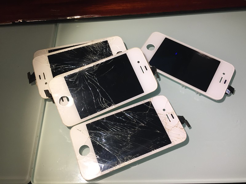
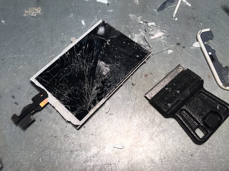
Okay folks, I already spent some cash ordering iPhone LCDs, connectors and an extension cable. However according to the leaked iPhone 4S schematic, the touch-screen is a whole different animal. It is on a separate connector, and the controller seems to be 100% custom. It uses some sort of grid matrix capacitive touch system which I currently can't find a matching controller to drive. The real Pip-Boy of course doesn't have a touch-screen. But without it, any functions outside of a dedicated Pip-Boy GUI would be difficult, requiring a bluetooth mouse.

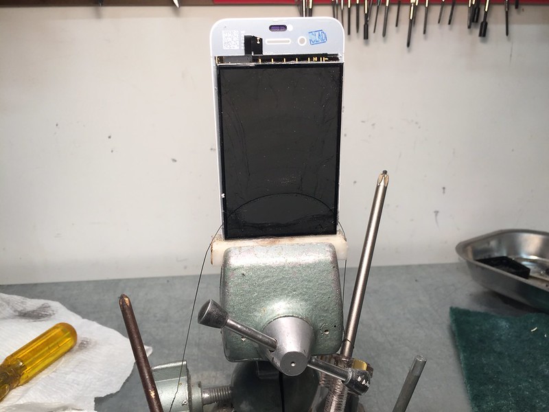
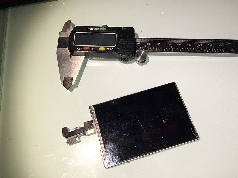
NewHaven Display sells a 3.5" single-touch resistive overlay for only $10. So I think I will have to design it so that this overlay can be placed on top of the iPhone display.
(For some reason they won't sell me the 2-touch, I2C, glass capacitive overlay they include on their 3.5" LCD screen that I have on my desk.)

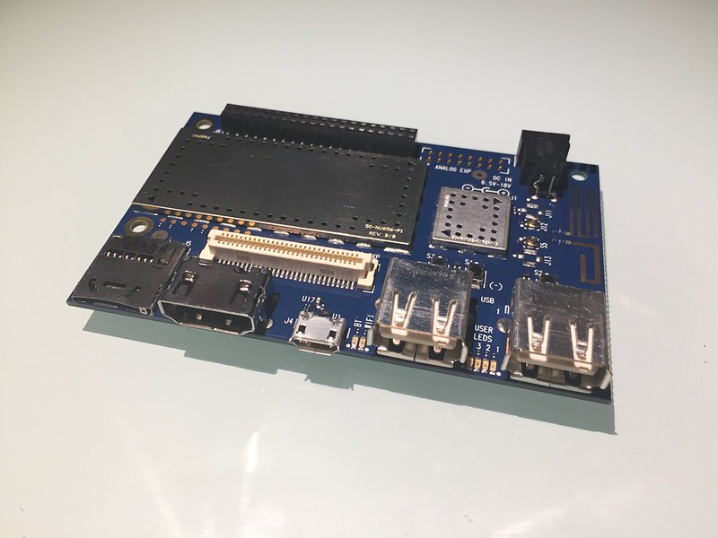
All of this assumes that the iPhone display will simply work with the DragonBoard 410c. But from what I have read the MIPI interface is designed to be rather universal.
It is really too bad that the two LCD displays I already have on my desk both require tons of work and complex circuits to interface with the DragonBoard.
 
I'll be putting together a Pip-Boy kit soon, and I'm wondering if you've considered paint options yet - if so, I'm curious to hear your thoughts. To my eyes the in-game color looks almost like the matte Bess Brown used on the Aliens pulse rifles and motion trackers. I don't mean to hijack your thread or anything to talk about projects that aren't yours...but given your intense commitment to accuracy with this thing, I think you're the best one to ask!
 
I haven't worked out any paint colors yet. The primary color in the rendering is taken from the game. (Captured outdoors in full sun light)
As far as techniques, I plan on following some of the excellent videos which Valcrow has posted on YouTube. I like the rock-salt rust technique he used on his lightsaber.

The SLS plastic starts out with a sandstone like consistency. But it can be sanded and polished to a high-shine. The plastic absorbs pigment almost as well as paper. This makes me think that using a thin airbrush paint will be the best option for most of the surface. I haven't used an airbrush, or painted a model since high school, so I will be re-learning a few techniques.

All the black parts will come pre-dyed in black, and they can be lightly sanded without removing the black. I probably will Vinyl Dye spray paint to touch up the black components. Really the rest of the Pip-Boy is a shade of brown with rust effects added.
 
Last edited by a moderator:
2ZeNviG.jpg


I have a new toy at the office. :D

At work we will be using it for prototypes and assembly jigs, but I also get to use it for other projects, if only to learn about how to work it better.
I still don't expect to 3D print the Pip-Boy on this machine, not the final model anyways. But it will help me to prototype some of the mechanical mechanisms such as the gears, retractable cable, and holotape cassette.

I have done a few test prints of hard to build objects, and it did better than I expected, but even at high quality the end result was still a rough sketch compared to a SLS part.
 
After reading trough the progress of the pip-boy design I find it awesome but am perplexed about the quote about android not running on raspberry pi, which is true for zero and ther original but not for Rpi 2 and 3 due to the different processors used

Original pi and zero have 700 MHz single-core ARM1176JZF-S
Pi 2 has 900 MHz quad-coreARM Cortex-A7
Pi 3 has 1200 MHz quad-core ARM Cortex-A53
 
Last edited by a moderator:
Perhaps the Pi3 (not released when I made my statements) could run Android 5.1, but there is no official release for it. There are a few old android builds for the other boards, but those wouldn't be new enough to run the companion app.

There is also the fact that the Pi3 is comparatively huge. It has double stacked USB and Ethernet connectors, 0.1" headers. The Pi is a good gateway for programmers to learn hardware interfacing, but they don't really encourage actual product integration or design. Instead Raspberry spends their resources encouraging people to build products using lots of pre-made kits.
 
I just crushed this thread this morning and am just a totally floored. Really inspiring work, here. Made me late for work, I just had to finish it! This is going to be one for the ages, Zap.


Sent from my iPhone using Tapatalk
 
​This weekend I attended the first ever Hackaday Hackathon here in Austin, TX. It was a great and memorable event. I met lots of great people working on their own projects.

The hackathon was held at the Silicon Labs office, which was perfect for me, as I was trying to get my hands on a Silicon Labs heart rate monitor, ever since i met one of their reps at a TechShop meetup.

I scored two development boards, both of which I can use in the Pip-Boy design.

-----------------------------


​The first is the Sensor Puck. This thing is great. It is a Bluetooth LE device. On-board it has a heart rate sensor, temperature sensor, and humidity sensor. The same heart rate sensor can also read UV index and ambient light if left exposed. As you can see in the image above, the board works out of the box. I can't say enough how much ready to use development boards like this help a non-programmer such as myself.


I have tried holding the monitor up to my wrist, with mixed results. It works sometimes if positioned directly over a vein, but not anywhere else on the arm. This chip was really designed more for reading a finger tip. Most wrist-mounted smartwatches typically use very powerful dual green LEDs to read your heart rate. So I may not be able to mount the sensor directly into the Pip-Boy armband. But it gets me a start on how these things works and if I can integrate the sensors.

/Edit: I noticed that the Si1147 chip does support external LEDs for the heart rate, so it sounds like I can boost the signal for use on the wrist.​

-----------------------------


The other development board I got was the EFM8 Busy Bee. This board comes with Space Invaders already installed. After a few minutes of playing around with that I only managed to get to level 4.

I may be able to use this dev board and chip to handle all the other stuff that the DragonBoard can't handle. Such as Analog input and LED PWM control. The board also has a five way joystick, which others have suggested I add to my project, It works well enough I may just try.
The best part is that Silicon Labs provides lots of support for their development boards.
 
Last edited:


​Today I received 6 cracked iPhone 4S LCD screens from eBay. The seller claimed they were all removed from functional iPhones. (Sure probably functional after the LCD was replaced)

In either case I didn't necessarily purchase them expecting them to work. No what I need right now is practice, and an accurate CAD model. I am also pretty sure that not one of these are actually authentic OEM displays. But if I get lucky and some work, then great.


​​-------------------------


​After watching a few videos on YouTube, on how to separate the glass from the LCD. I took two of the LCDs which looked the worst off. One LCD had the ribbon cable separated, and the other had visible cracks in the LCD as well as the top glass. I am sure neither of these displays are functional. Before trying to separate the glass I put on leather gloves and eye protection.

On the first display I tried a method where you heat the display, and draw a cheese cutting wire behind it.

This first display separated a bit too easily. I think that it was a low quality fake, as the backlight basically fell off with very little effort, and the polarizer was plastic.

​​-------------------------


For the second display I tried a more careful, but tedious method. I first heated the surface of the display to about 60C. Then, using a razor, I gently lifted the cracked glass away from the LCD. Gently heating up one section at a time and then removing a small area of top glass.


​​-------------------------


​After about thirty minutes I was able to remove all the top glass. I did manage to chip two of the corners, and next time I will take more care with those. Hence, purchasing these for practice.

​​-------------------------


In the case of this display, the underlying polarizer was actually glass. This allowed me to scrape most of the adhesive off with the razor, and then clean it up with a scotch pad and denatured alcohol.

This display will be used to develop a CAD model of the actual LCD.

I have found at least one Hong Kong supplier who lists the raw LCD without digitizer or top glass. But they haven't replied to e-mail for two days now, and as usual simply list the display in hopes I will accept a different in-stock model.


​Today I came home to the Qualcomm DragonBoard 410C waiting for me. Thanks to everyone who voted for my project on their contest page. Apparently there is a 2nd round, but I don't know if I will make their deadline. I do want to get cracking on using this board, but that will have to wait until the weekend. I also need to design a board that attempts to connect the MIPI interface to the iPhone 4S LCD.


----------------------


I also received a box of parts from McMaster-Carr. Note that the Bill-of-Materials lists that all these parts should cost around $40, but due to minimum quantities it actually costs $180 to order all these parts.

----------------------


I also 3D printed my first set of prototype parts. These were printed at 0.1mm layer height with a 0.4mm nozzle on a Ultimaker 2. It took over three hours to print the parts. My goal here is to get a feel for the parts before I order them in SLS Nylon. My first impression...these parts are smaller than I expected.

----------------------


​I cleaned up the 3D prints. For the most parts these are accurate enough to determine if I need to make any changes to the CAD model. As you can see even at 0.1mm resolution, the parts just don't compare to the smooth finish of the SLS printed Holotape above.

----------------------


​First I attached the button cap to the switch. It fits perfectly. The PLA plastic did crack, as it is fairly brittle, but it did work.


I then tested the snap-fit connection on the Potentiometer. The problem is that to make the snap-fit work, I had to remove material from the middle of the shaft, which also in-turn weakened it. So this won't work even in flexible nylon, not without risking the shaft snapping.

----------------------


​My solution is to beef up the shaft all the way to the body of the pot. Then the smaller D-shaped portion passes through the shaft. Finally a C-Clamp will hold the shaft in place behind the pot. This way the assembly can also be tested without worrying about a snap-fit failing after a few uses.

----------------------


​Now onto some of those new McMaster parts. And no that isn't a novelty sized lighter, sneeze and these parts go flying.

Above is a 2mmx8mm Captive pin. These pins are normally used sheet metal, but they will work well in plastic. However, because the PLA plastic shrinks, the pin doesn't fit into the hole. The solution is to heat up the pin using a lighter. Then once the pin is hot, very carefully push the 3D printed piece onto the pin.

----------------------


​The pin will melt the plastic enough to pass through. As you can see above, a few parts got a bit too hot. But they will still serve their function well enough. Once cooled the pin is a tight fit, but can pull out. Some superglue can be used to set it securely.

Using this method you can set real metal pins into plastic. And they won't snap off like a plastic formed pin. They also will turn much easier.

---
 
Last edited:
Been following this post for months now back on page 4 I want to say. and I was wondering if when you get to the point of kit selling, if it would be possible to have a pack of the models that could be printed on an extrusion based 3D printer.I know you have said over and over that SLS parts are much better in terms of detail and cleanup, but for those who don't mind extra cleanup (such as myself being a prop maker) printing off the much cheaper and widely availible desktop 3D printers would be much easier for most people. again, I know the tolerences wouldnt all match up, but wheres the fun in eerything being seamless?
 
Looking good.

I went through your interest-survey-thingy a couple of days ago and was horrified to find my lower arms are too big! Not by much, but enough :( Damn you muscle mass!

Still! Looking forward to seeing this progress.
 
Mew14: It may end up being that I only sell the hardware and electronics as a kit, and people can select to 3D print the parts themselves or order them from my shop on Shapeways.

That way people can decide for themselves what quality level they want. The particular parts above do work "okay" with a FDM printer. The real test will be when I start printing the main body, which has many tiny internals features used to hold the electronics in place. FDM printers can't really handle that level of detail without spending several days on a single print.
loonitick, The arm size is pending final dimensions. I have opted to skip on the padding on the first run, so the final arm size will be a bit larger. The padding can always be added later.
 
Last edited by a moderator:
zapwizard:
Where do you get those tiny flat pots from? I have a couple of designs in the pipework that would benefit greatly from some bits like that.
 
Last edited by a moderator:
loonitick: They are Bourns 3382G-1-103G, you can get them at Mouser.com. They are the smallest 360 turn pots I have ever seen. You can get them in Surface Mount and Through-hole versions, as well as different resistance values of course.

Just since it's in the same post: The push button switch I am using is a Panasoinc ESE20C441. I selected it because it has a huge 2.5mm travel distance and relatively high operation force. This means the top button on the Pip-Boy won't have some stupid little "click?", instead it has a very satisfying "click!"

The captive pins are McMaster 95648A340. They darn expense expensive as far as pins go. ($0.36ea), but the little shoulder they have means they won't work their way out of the part once properly set. They also have a very nice chamfer at the top, which most small pins don't have.
 
Last edited by a moderator:

26199301394_9ba267e3e5_c.jpg


This post will also be my first set of video updates. I will also type out the details.
I designed a bunch of test rigs to be 3D printed on the Ultimaker 2. Each part designed to test a specific part of the design.

The first test is for the geared down radio knob, FDM 3D print was pretty rough, but did the job. The three gears mesh together and the gearing works great. There is very little to change on this area of the design.

-----------------------------------------

26803993945_47457b6844_c.jpg


I printed up the communications link cable for testing. One thing I forgot was to add tolerance to the threads, and so the first print got stuck and had to be forcefully separated. Adding 0.2mm of tolerance made the parts fit together perfectly. The bayonet connection works nicely, and holds tight. Once docked it doesn't come loose until you want it. As mentioned when I designed this part, I did a reverse thread, that way if you need to somehow use more force to turn it, the black and white parts won't separate. See the video below showing how the test piece fits together.

-----------------------------------------

(Sorry about the audio on this one, next time I will use my good camera instead of my phone)

26199302964_0275dfe0ed_c.jpg


Now the cable retraction mechanism was both a success and failure.
The actual cable lock, pawl and spool all work well. I will make some changes to get the wire to wrap a bit better without jamming.
However, the spring I selected was just not designed for this type of retraction. What I need is a spiral torsion spring. However, I can't find any of these available retail, they all seem to be custom. I have a one-way retracting charger cable in my car, which I may rip apart just to see if the spring is useful, the other option is to rip apart a cheap tape measure, as they have the proper spring, although it would be far longer than I need. I will have to think about the whole mechanism a bit more. But that is what prototypes are for.
 

Attachments

  • 26199301394_9ba267e3e5_c.jpg
    26199301394_9ba267e3e5_c.jpg
    139.4 KB · Views: 132
  • 26803993945_47457b6844_c.jpg
    26803993945_47457b6844_c.jpg
    126.9 KB · Views: 130
  • 26199302964_0275dfe0ed_c.jpg
    26199302964_0275dfe0ed_c.jpg
    154 KB · Views: 126
  • 26199301394_9ba267e3e5_c.jpg
    26199301394_9ba267e3e5_c.jpg
    139.4 KB · Views: 134
  • 26803993945_47457b6844_c.jpg
    26803993945_47457b6844_c.jpg
    126.9 KB · Views: 123
  • 26199302964_0275dfe0ed_c.jpg
    26199302964_0275dfe0ed_c.jpg
    154 KB · Views: 123
  • 26199302964_0275dfe0ed_c.jpg
    26199302964_0275dfe0ed_c.jpg
    154 KB · Views: 126
  • 26803993945_47457b6844_c.jpg
    26803993945_47457b6844_c.jpg
    126.9 KB · Views: 129
  • 26199301394_9ba267e3e5_c.jpg
    26199301394_9ba267e3e5_c.jpg
    139.4 KB · Views: 126
Last edited by a moderator:

26219829514_75ab227537_c.jpg


Today I printed up the holotape test mechanism. I designed the first version of this way back in August. It is really satisfying to see it working in the real world. There are some tweaks to be done. Currently the springs aren't tight enough (They had to be shortened in the test rig). The closing is a bit rough. And it can jam if the Holotape is in just the wrong position. But otherwise, the design actually works!
 

Attachments

  • 26219829514_75ab227537_c.jpg
    26219829514_75ab227537_c.jpg
    157.3 KB · Views: 115
  • 26219829514_75ab227537_c.jpg
    26219829514_75ab227537_c.jpg
    157.3 KB · Views: 113
Last edited by a moderator:

Your message may be considered spam for the following reasons:

If you wish to reply despite these issues, check the box below before replying.
Be aware that malicious compliance may result in more severe penalties.
Back
Top