Functional Pip-boy 3000 Mk IV from Fallout 4

27492085605_b68b54c530_c.jpg


Hey Folks, it has been a month since I posted an update. Real-life is getting busy again. But I did find time to go in an fix issues with my first round of prototypes.

------------------------------


27457724776_f17e5c46bd_c.jpg


The radio knob assembly was re-designed such that the needle and the electronically read potentiometer were directly connected. In the first build they were separated by a secondary gear, and so if a gear tooth ever slipped the readout would be inaccurate. The new design works very well and is more robust. I also managed to print up some temporary gauge faces. Everything with this prototype works well, so I don't expect any more changes to this part of the design.

------------------------------

27492086335_86c34aa971_c.jpg


The Holotape cassette mechanism was next. I managed to fix the closing mechanism, and all the springs. But when there is too much friction in the system the eject mechanism can get caught up during opening. I may make a few more tweaks to ensure the mechanism is robust and can't get caught up. Otherwise the design is close to finished.


------------------------------

27457725316_58587e1d53_c.jpg


The cable retraction mechanism unfortunately is a different story. I did make some improvements, such as adding a guide for the cable to reel into.
I also removed a spring from a 3ft tape measure, it was the perfect size, however the spring simply isn't strong enough to overcome all the fiction in the system. The reel will feed out and retract if the catch isn't installed, or the slip-ring PCB, but just barely. If the spring were about 3x stronger than the mechanism would work great. However, I can't find any small (20mm Dia x 6mm Thick) springs which are stronger than I have now.

The 3mm thick cable also plays a part in the friction. I have taken apart a retractable USB car-charger which works very much the same as my mechanism and using a smaller spring, but it also uses a much thinner cable. That thinner cable doesn't look game accurate to my eyes, and it only has two wires so would only support charging, and no actual data. Still reverse engineering the car charger has gave me a few ideas, so I will take one more crack at this mechanism to see if I can get it all working.

------------------------------
 

Attachments

  • 27492085605_b68b54c530_c.jpg
    27492085605_b68b54c530_c.jpg
    277.7 KB · Views: 389
  • 27492086335_86c34aa971_c.jpg
    27492086335_86c34aa971_c.jpg
    132.2 KB · Views: 109
  • 27492086335_86c34aa971_c.jpg
    27492086335_86c34aa971_c.jpg
    132.2 KB · Views: 112
  • 27492086335_86c34aa971_c.jpg
    27492086335_86c34aa971_c.jpg
    132.2 KB · Views: 116
  • 27492086335_86c34aa971_c.jpg
    27492086335_86c34aa971_c.jpg
    132.2 KB · Views: 130
  • 27457724776_f17e5c46bd_c.jpg
    27457724776_f17e5c46bd_c.jpg
    115.6 KB · Views: 139
  • 27457724776_f17e5c46bd_c.jpg
    27457724776_f17e5c46bd_c.jpg
    115.6 KB · Views: 113
  • 27492085605_b68b54c530_c.jpg
    27492085605_b68b54c530_c.jpg
    277.7 KB · Views: 127
  • 27492085605_b68b54c530_c.jpg
    27492085605_b68b54c530_c.jpg
    277.7 KB · Views: 130
  • 27492085605_b68b54c530_c.jpg
    27492085605_b68b54c530_c.jpg
    277.7 KB · Views: 126
  • 27457724776_f17e5c46bd_c.jpg
    27457724776_f17e5c46bd_c.jpg
    115.6 KB · Views: 143
  • 27457724776_f17e5c46bd_c.jpg
    27457724776_f17e5c46bd_c.jpg
    115.6 KB · Views: 131
  • 27457725316_58587e1d53_c.jpg
    27457725316_58587e1d53_c.jpg
    130 KB · Views: 158
  • 27457725316_58587e1d53_c.jpg
    27457725316_58587e1d53_c.jpg
    130 KB · Views: 131
  • 27457725316_58587e1d53_c.jpg
    27457725316_58587e1d53_c.jpg
    130 KB · Views: 131
  • 27457725316_58587e1d53_c.jpg
    27457725316_58587e1d53_c.jpg
    130 KB · Views: 139
Last edited by a moderator:
For the cable spool, could doubling up the spring work? As in, fit 2 identical concentric springs. As long as they are lubricated/greased before assembly friction between them should be negligible while increasing spring force considerably. Sorry if you have already tried that, just thinking on my feet, had/having similar problems with some of my own designs.
 
loonitick, I have looked for thicker (not wider) springs without luck, but I didn't really think of combining them. I will try that tonight and see if it works.
If that doesn't work, I am going to try taking apart a much larger tape measure, and then cutting down the spring to 6mm wide. Spring steel is fairly brittle, in that if you bend it too far it just snaps, I am hoping I can cut it using tin snips or maybe a guillotine style paper cutter.

I took apart my retractable car-charger. It uses a thicker metal spring, but that spring was also much narrower in height. When I turned it by hand it didn't feel any stronger than what I am using now. Otherwise, there wasn't much to learn from it other than perhaps the thinner cable, and using a double-sided reel to help ensure the cable doesn't bind up against one surface.
 
Last edited by a moderator:
Well I tried the double spring idea which loonitick suggested. Let me tell you winding one of those razor sharp springs is scary... so trying to wrangle two of them, ya that was hard.
I did managed to get it wound up, and indeed it is stronger, and helps, but alas not enough to overcome all the combined friction. I am going to keep on searching for a stronger yet same diameter spiral torsion spring. (20mm OD, 6mm Wide). I will also make a few design tweaks this weekend and see if I can't lower the total amount of friction.
 
Last edited by a moderator:
26922913304_59b07413b6_c.jpg


Hey folks,

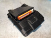
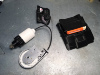
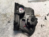
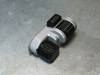
I finished up another set of functional prototypes. This time for the selection knob, scroll wheel and select button. These worked perfectly as designed, and very little will need to be adjusted. The detents in the scroll wheel and selection knob feel great. The huge throw on the switch is also satisfying. I didn't think that the little details required to hold the potentiometers in place would even be possible on a FDM printer, but the part came out surprisingly good. I only had to ream out the various holes, and file away a few stray bits of plastic. The only change I want to make is to try and beef up the macro knob shaft. Currently it wobbles too much for my taste. As much as I like the 360 turn pots, I may switch the knob back to a normal panel mount type pot; if only so that there is a metal shaft instead of plastic.

--------------------------------------------------

27497994056_142eb1ab29_c.jpg


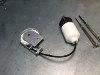
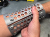
I also printed up the internal arm band, if only to ensure that the Pip-Boy will actually fit onto my arm. It does fit, but will be tight near my forearm, and require padding near my wrist. This tightness is actually required if I locate the heart-rate monitor on the inside of the Pip-Boy.

I am still very much lost on the best way to secure the Pip-Boy to my arm. I don't want the Pip-Boy to be able to rotate out of position like a heavy watch, and this will be a VERY heavy smartwatch.

Here are my ideas so far:
1) Design a form fitting 3D printed structure. I may even go as far as mold my arm and then 3D scan it to get a perfect fit. A velcro strap would be used as backup to the latch.
2) Just try to add padding as in the game model. The padding would have to have variable thickness. I worry however that even with a loose knit thread, that any padding will make it very hot under the Pip-Boy.
3) Design a magnetic gauntlet. Strong magnets in the gauntlet would mate with magnets in the arm band. I like this idea as the gauntlet could be made to look like the in-game leather armor. The magnet would hold the Pip-Boy steady, and if strong enough replace a velcro backup. I could even put the heart-rate monitor and other bio-feedback sensors into the gauntlet. However this idea still has the problem of not breathing, however sweating is apparently step one in any cosplay costume.

Note, I will NOT be adjusting the design to make it one size fits all. It isn't as simple as scaling up the 3D model, as all the electronics are effectively fixed in place. If I go with idea #1, I will release 3D files that allow you to design your own Pip-Boy to Arm interface.
 

Attachments

  • 26922913304_59b07413b6_c.jpg
    26922913304_59b07413b6_c.jpg
    105.2 KB · Views: 129
  • 26922913304_59b07413b6_c.jpg
    26922913304_59b07413b6_c.jpg
    105.2 KB · Views: 120
  • 26922913304_59b07413b6_c.jpg
    26922913304_59b07413b6_c.jpg
    105.2 KB · Views: 123
  • 26922913304_59b07413b6_c.jpg
    26922913304_59b07413b6_c.jpg
    105.2 KB · Views: 140
  • 27497994056_142eb1ab29_c.jpg
    27497994056_142eb1ab29_c.jpg
    133.9 KB · Views: 117
  • 27497994056_142eb1ab29_c.jpg
    27497994056_142eb1ab29_c.jpg
    133.9 KB · Views: 148
  • 27497994056_142eb1ab29_c.jpg
    27497994056_142eb1ab29_c.jpg
    133.9 KB · Views: 110
  • 27497994056_142eb1ab29_c.jpg
    27497994056_142eb1ab29_c.jpg
    133.9 KB · Views: 124
Last edited by a moderator:
Epic progress. Wish I could follow the post more often.

As far as options for padding what about direct casting soft polyurethane foam between your arm and that arm band. Would be simple as using plastic wrap on your arm and outside of arm band. Then pour the foam mix into the cavity and allow to expand.
For comfort you can cut holes into it and use contact cement to attach a felt or other fabric where your skin touches it. http://www.reynoldsam.com/product/flexfoam/ This site sells a lot of different foams and the sample size is 2 coke can sized bottles. That much resin would make 7 or 8 inserts.

As far as the magnets there are several options but these magnets are 0.25x0.25x0.1inch and exert 2.41 lbs each so 2 magnets acting on each other would be about 4.25 lbs

I hesitate to mention it but what about mounting a small spring in the bottom of the halo deck. A small spring (low force) would kick the disk out just a little to aid in extraction and all a user would have to do is hold a halo disk in with their thumb while pressing the drive down to close it.
 
m9365428,

Great idea on just pouring foam to make form fit padding. I could even have the padding mate with a 3D printed structure to secure the foam to the Pip-Boy. I could then carve it to look close to the game model, while still having a custom fit.

As far as the holotape, when it opens there is actually a kicker, basically the holotape itself hits the back of the Pip-Boy and this pushes it out automatically. I have messed with my prototype part a bit more and I think I was just getting some friction from the imperfections in the FDM plastic. Once made in SLS nylon it should work perfectly.
 
Last edited by a moderator:
Ok didn't know that and glad I could help with at least one good idea.

If your having friction problems on your parts you can polish them or add a little graphite powder. There are plenty of instructions for polishing prints out there but here is a demo video
For ABS parts acetone is best (hardware store)
For PLA a better alternative is Tetrahydrofuran (amazon)

process is the same with either material just different solvents
 
Hey did you see this yet? Just ran across it.
https://www.youtube.com/watch?v=77XLgPKbK5M

I was gonna post the same thing, saw it this morning! Big slap in the face for everybody who bought the Pip Boy Edition, this is how it should have been imo!

And from that I can tell it even is exactly the same mold, just with a few more details and working electronics! It even uses the same ****ty brownish plastic from the Pip Boy Edition! :D
 
Just got it in my e-mail... I want to rip one apart just to see if they stole any ideas. :devil
It does look like the same mold, they probably just altered the interior parts. Which means it isn't game-accurate. Except for that huge screen. I want that screen! It looks like there is even a slightly curved lens over the screen. It looks like it does have a USB docking connector built into the stand, that is nice.

My issues:
-STill not game accurate
-WTF is up with the brown holotape being inserted backwards? (It's apparently a USB key also)
-The latch is black, which means it most likely is plastic and not cast zinc
-Same velcro attachment which doesn't work well.
-Black paint on the metal heatsink fins
-Radio knob will still be 1:1 movement
-Non-functional rad gauge
-Holotape is a simple hinge, not a pop-up cassette holder
-"Doesn't interface with the game"

I can't afford $350 right now, so if someone gets one please give me details when you get it.
Since this is "Functional" it may change my ability to sell kits under fair use..so I will have to think about a way around that.
 
Last edited:
If this rinky-dinky thing kills the chances of putting together a Zap-Boy I'm going to be so sad :( To me, putting the thing together is 3/4 the fun. But yeah, that screen tho... ;) Gotta find out which factory in China they're buying them from!
 
I can't afford $350 right now, so if someone gets one please give me details when you get it.
.


You can pre order from Thinkgeek. They won't charge you until it's ready to ship. Ordering from Bethesda's site, you'll have to pay right then and there.


Wanted to add some thoughts here. The new versions are cool (got two on pre order myself), but they still lack a few features Zap's pipboy will have. No retractable white pod cable thingy on the official version, and while the tape deck is much improved, honestly it looks a little cheap when opened up. And it will still have those little detents/key slot holes for the stand to lock into (ugh). With two smartphone pipboys and two blue tooth pipboys on the way, I am most certainly still looking forward to building a zapwizard pipboy.


But...........yes. That screen. :love
 

Your message may be considered spam for the following reasons:

If you wish to reply despite these issues, check the box below before replying.
Be aware that malicious compliance may result in more severe penalties.
Back
Top