I was only going to do a build log on one board, but figure would do it here also. More people visit these boards, and I am always looking for feedback, and help on odds and ends. Some quick history, I saw Neil Smith's Not Your Average Falcon and was over awed by what he had accomplished. Thus, seeing what could be done, and having my imagination fired up, I started listing everything I wanted my Falcon to do.
Here is the beginning of the electronic capability I am looking for the model to do. The list is going to grow.
IR Remote Control
Music
Not Sure if I want voice overs - Kind of Cool though
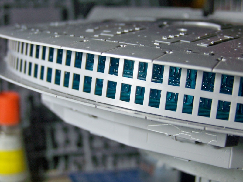
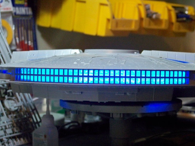
Engines - I plan on using RGB LEDs to make multiple colors on the engine output -
Watching SW a few times they go from a dark red to a darker blue to almost a pure white as the power ramps up, some of the shots show almost a yellow tinge in SW. Need to look at Empire a ROTJ.
Motorized Ramp - As part of certain sequences and automatic behavior
Motorized Landing Gear - need to investigate
Motorized Belly Gun
Motorized Radar Dish - need to investigate
Motorized Quad Laser Turrets - need to investigate
Smoke generator
Modes I want
Standard Power is On In Flight Mode - Basically what it looks like in 'static' flight.
Interior Lighting
Active Cockpit
Engine lights on
Need to figure out what external lights are on in flight mode - need to watch the movies!
Landing Sequence
Engine effects
Flood Lamps
External Lamps
Ramp automatically comes down
Internal Lighting
Inactive Cockpit
Options While Landed
Failed Engine Start
Active Cockpit
Engine flicker with sound effects
Smoke?
Failed Falcon Repair
Flickering fibers with sound effects
Belly Turret Gun - If I can do it, will try!
Control with remote control
Fire and move with sound effects
Take Off Sequence
External Lamps Off
Cockpit goes active
Ramp goes up
Engines fire up
Delay then
Fly by sound and engine effects
Need to leave engine lights on - at the end of the take off in static flight mode
So more research into the behavior of the model. When I get it ironed out more, will put it into a software development looking format.
NEXT POST
Started mocking up the hardware to work on the engine effects. Part of the problem is that I really don't have all the electronic 'stuff' I used to have, so, having to rebuild some of that capability. It is a lot cheaper today than though in the past, love Amazon Prime and the fact that so many people use the Adruino and Raspberry Pi to do this stuff, the market has grown and increased competition.
So, I have been doing a lot of research on how to do what I want. I had a 900 mile drive yesterday, going to Board Game Geek Con today, woohoo, oh, and visiting family, and thought a lot about the model and what it is going to take.
I looked at stepper motors and servos for movement. Basically, I would have to turn the stepper motor into a servo to get the functions I need, which include, mainly, knowing where within its movement rotation it is, and servos have all of that built in and take less wires. So, all but one of the movement requirements will use a servo.
Here is my updated list. I am still looking for really small servos and stepper motors. I have found some, but, I don't have access to the model for 2 weeks, so I don't know if I can get this all to fit in. Also, I am going to put all electronics in the base, which means I will have a mounting pole that is wide enough to house all of the wires. Which means, I will have to do a better job getting those wires smaller and less of them compared to my E.
So, I decided to list stuff as capabilities, to be used however I wanted. Hopefully that will make more sense farther down below.
If I can at all help it, there will a common ground, so, only 1 ground wire this time.
Retractable Landing Gear
5 x Servos
Power - 3.3V or 5V or other?
Ground
5 control wires
I want to laser scan the inside of the bottom hull section, so I can design perfect mounting platforms for the servos. I actually brought my model to work, and discussed landing gear with a PhD who does robotics, an ME with a PE, and an EE. LOL, best discussion and problem solving session of the day, for all of us. We had a few sketches on how the gear could work. The gear will have to lower and raise, and I want the gear covers to cover everything up in the up position and to flare open in the down position. plan on using Shapeways to make the parts.
6 wires total
Retractable boarding ramp.
1 x Servo
Power - 3.3V or 5V or other?
Ground
1 control wire
2 LED circuits, one for the lighting in the boarding area, and maybe one for an R2 unit in there, I think I can get him lit from the inside, need to see it it would be worth it, very tiny model.
3 wires total
Retractable belly turret gun
2 or 3 servos, depends on what we come up with for the door opening and turret lowering mechanism
Power - 3.3V or 5V or other?
Ground
2 or 3 control wire
1 LED circuit and fiber for the flash effect
4 wires worst case, most likely case though.
Upper Turret Stuff
1 DC stepper motor to rotate turret assembly.
4 wires
1 servo to raise and lower the quad cannon
Power - 3.3V or 5V or other?
Ground
1 control wire
2 LED circuits for the quad cannon, in the movies they fire in pairs, so I want to do the same, will also need fiber.
1 - 4 LED circuits for lighting in the turret well. I know that when I simulate the escape from the DS, that the interior lights need to flicker when the Falcon gets hits. Also, not sure if there were flickering lights i the turret well.
The elephant in the room though is getting all of this to fit into the well, and have it rotate. I been thinking about the mechanism to get the turret to rotate. Would be cool if it can all work. It is such a small part though.
11-12 wires for this?
Landing Lights
1 LED circuit
1 wire
This will turn on the floods and red lights around the bottom of the falcon.
These also need to be a 3K kelvin type light, very yellow looking as in the movie.
1 wire
Front spot lights
1 LED circuit
These looked to be very white, think 5K kelvin type of light.
1 wire
Failed repair effect
1 LED circuit
The LED will be hooked to some fiber to flash as in the movie.
1 wire
Fog effect
I don't know power requirement
Will have to have access to fill reservoir for smoke liquid
I think 1 wire to just turn it on and a little pump?
1 wire, maybe two. I have not looked into this at all.
Cockpit
General lighting
C-3PO lighting
I need to do more research and see if any of the cockpit lights blink etc. I can add some blinking lights. Since the cockpit tube is supposedly removable, I would put a blinking board in the tube, if it fits.
3 wires, maybe more, not sure, more work required.
Motorize radar dish.
I would like this rotate and maybe raise and lower.
2 x Servos
Power - 3.3V or 5V or other?
Ground
2 control wires
I don't think I left anything out, maybe?
So 11 or so servos, a stepper motor, smoke box, lots of LEDs, blinky board and other stuff. If I can get it all to fit, I will put it in. Lots of design work to get the gear and other movey things movey.
NEXT POST
Well my vacation is over, and I am back at the house. The good thing, I was able to stop by several hobby stores and locate some really small servos. I bought a DS35 digital super sub-micro servo made by E-flite and a 1.9 gram linear long throw servo made by Spektrum. Pics attached. I also got my work area cleaned up today, and my development area going. I had to upsize the table, not enough room for everything. I need to go get an oscilloscope though, anyone have a cheap one for sale?
I ordered some parts from Shapeways that are ultra detail interior components for the model, when I get some primer on them, I will take some photos. They don't show up very well in clear plastic.
I have the stock parts, the photo etch and these parts from Shapeways, looking forward to reviewing all three.
At first glance though, the Shapeway parts are absolutely amazing.
Since I can now print such ultra detail parts, I came up with a design for the landing gear mechanisms. the hard part is to go from a napkin design to something that can be printed. Luckily, since Shapeways business model is to sell you printed 'stuff' they have a lot of options to go with. I choose the AutoDesk , I taught myself AutoCAD many moon ago, so hopefully some of that will come back, and I can drive it half decently. When I have something worth showing on how the gear will work, I will put a pic or two up here.
The design has to be relatively compact, so as to fit in the model, I think I have it. I also want the 'doors' that cover the landing gear on the bottom to open and close when the gear drops and retracts. I 'think*' I have an idea that will work for that. Just need to get it into this CAD program and print it and test it.
The prices for the parts are not too crazy expensive, so hopefully, knowing I will need a few iterations, I won't go broke getting this to work.
When I have the design done, will post and discuss. Off to work on said design.
Oh, AutoDesk, also has a really easy PCB layout program, which will be instrumental in the Enterprise and Reliant build, not so sure on this one. I might do a PCB board will everything plugs into a board, for easy removal of the Adruino control board, don't know. I need to see how hard it is to use and what it costs to get one of these boards made though. More on that much later in this build.
Pics show the small size of the servo and the third pic is of it working, although there isn't video attachment capability here.
Also took a few shots of the servo inside the model, next to the gear wells. I am soo happy to have found these guys, I just hope they have the oomph to move the gear.


- - - Updated - - -
This little picture may not look like much, but holy C@$P it took a lot of effort to make. This is the housing for the landing gear mechanism that goes inside the Falcon. It isn't done, but hopefully you get the idea of how I am going to translate radial motion into linear motion. I need to do some more work on the servo mounting pad, and do some work for the linear servo that will open and close the landing gear bay doors.
This will be printed out at Shapeways, hopefully have the design done by the end of the week for the first landing gear. Get it printed and tested.
I switched from 123D to FreeCAD. I couldn't do dimensions in 123D, and you can in FreeCAD.
Here is the last part. I ordered everything from Shapeways, super easy to do. Should get it in 2 weeks-ish or so. Hopefully everything works well when the stuff arrives. Need to work on the code now to run the servos. That should be done before the parts show up, so I only have to debug the mechanical bits and not the code.


Here is the beginning of the electronic capability I am looking for the model to do. The list is going to grow.
IR Remote Control
Music
Not Sure if I want voice overs - Kind of Cool though
Engines - I plan on using RGB LEDs to make multiple colors on the engine output -
Watching SW a few times they go from a dark red to a darker blue to almost a pure white as the power ramps up, some of the shots show almost a yellow tinge in SW. Need to look at Empire a ROTJ.
Motorized Ramp - As part of certain sequences and automatic behavior
Motorized Landing Gear - need to investigate
Motorized Belly Gun
Motorized Radar Dish - need to investigate
Motorized Quad Laser Turrets - need to investigate
Smoke generator
Modes I want
Standard Power is On In Flight Mode - Basically what it looks like in 'static' flight.
Interior Lighting
Active Cockpit
Engine lights on
Need to figure out what external lights are on in flight mode - need to watch the movies!
Landing Sequence
Engine effects
Flood Lamps
External Lamps
Ramp automatically comes down
Internal Lighting
Inactive Cockpit
Options While Landed
Failed Engine Start
Active Cockpit
Engine flicker with sound effects
Smoke?
Failed Falcon Repair
Flickering fibers with sound effects
Belly Turret Gun - If I can do it, will try!
Control with remote control
Fire and move with sound effects
Take Off Sequence
External Lamps Off
Cockpit goes active
Ramp goes up
Engines fire up
Delay then
Fly by sound and engine effects
Need to leave engine lights on - at the end of the take off in static flight mode
So more research into the behavior of the model. When I get it ironed out more, will put it into a software development looking format.
NEXT POST
Started mocking up the hardware to work on the engine effects. Part of the problem is that I really don't have all the electronic 'stuff' I used to have, so, having to rebuild some of that capability. It is a lot cheaper today than though in the past, love Amazon Prime and the fact that so many people use the Adruino and Raspberry Pi to do this stuff, the market has grown and increased competition.
So, I have been doing a lot of research on how to do what I want. I had a 900 mile drive yesterday, going to Board Game Geek Con today, woohoo, oh, and visiting family, and thought a lot about the model and what it is going to take.
I looked at stepper motors and servos for movement. Basically, I would have to turn the stepper motor into a servo to get the functions I need, which include, mainly, knowing where within its movement rotation it is, and servos have all of that built in and take less wires. So, all but one of the movement requirements will use a servo.
Here is my updated list. I am still looking for really small servos and stepper motors. I have found some, but, I don't have access to the model for 2 weeks, so I don't know if I can get this all to fit in. Also, I am going to put all electronics in the base, which means I will have a mounting pole that is wide enough to house all of the wires. Which means, I will have to do a better job getting those wires smaller and less of them compared to my E.
So, I decided to list stuff as capabilities, to be used however I wanted. Hopefully that will make more sense farther down below.
If I can at all help it, there will a common ground, so, only 1 ground wire this time.
Retractable Landing Gear
5 x Servos
Power - 3.3V or 5V or other?
Ground
5 control wires
I want to laser scan the inside of the bottom hull section, so I can design perfect mounting platforms for the servos. I actually brought my model to work, and discussed landing gear with a PhD who does robotics, an ME with a PE, and an EE. LOL, best discussion and problem solving session of the day, for all of us. We had a few sketches on how the gear could work. The gear will have to lower and raise, and I want the gear covers to cover everything up in the up position and to flare open in the down position. plan on using Shapeways to make the parts.
6 wires total
Retractable boarding ramp.
1 x Servo
Power - 3.3V or 5V or other?
Ground
1 control wire
2 LED circuits, one for the lighting in the boarding area, and maybe one for an R2 unit in there, I think I can get him lit from the inside, need to see it it would be worth it, very tiny model.
3 wires total
Retractable belly turret gun
2 or 3 servos, depends on what we come up with for the door opening and turret lowering mechanism
Power - 3.3V or 5V or other?
Ground
2 or 3 control wire
1 LED circuit and fiber for the flash effect
4 wires worst case, most likely case though.
Upper Turret Stuff
1 DC stepper motor to rotate turret assembly.
4 wires
1 servo to raise and lower the quad cannon
Power - 3.3V or 5V or other?
Ground
1 control wire
2 LED circuits for the quad cannon, in the movies they fire in pairs, so I want to do the same, will also need fiber.
1 - 4 LED circuits for lighting in the turret well. I know that when I simulate the escape from the DS, that the interior lights need to flicker when the Falcon gets hits. Also, not sure if there were flickering lights i the turret well.
The elephant in the room though is getting all of this to fit into the well, and have it rotate. I been thinking about the mechanism to get the turret to rotate. Would be cool if it can all work. It is such a small part though.
11-12 wires for this?
Landing Lights
1 LED circuit
1 wire
This will turn on the floods and red lights around the bottom of the falcon.
These also need to be a 3K kelvin type light, very yellow looking as in the movie.
1 wire
Front spot lights
1 LED circuit
These looked to be very white, think 5K kelvin type of light.
1 wire
Failed repair effect
1 LED circuit
The LED will be hooked to some fiber to flash as in the movie.
1 wire
Fog effect
I don't know power requirement
Will have to have access to fill reservoir for smoke liquid
I think 1 wire to just turn it on and a little pump?
1 wire, maybe two. I have not looked into this at all.
Cockpit
General lighting
C-3PO lighting
I need to do more research and see if any of the cockpit lights blink etc. I can add some blinking lights. Since the cockpit tube is supposedly removable, I would put a blinking board in the tube, if it fits.
3 wires, maybe more, not sure, more work required.
Motorize radar dish.
I would like this rotate and maybe raise and lower.
2 x Servos
Power - 3.3V or 5V or other?
Ground
2 control wires
I don't think I left anything out, maybe?
So 11 or so servos, a stepper motor, smoke box, lots of LEDs, blinky board and other stuff. If I can get it all to fit, I will put it in. Lots of design work to get the gear and other movey things movey.
NEXT POST
Well my vacation is over, and I am back at the house. The good thing, I was able to stop by several hobby stores and locate some really small servos. I bought a DS35 digital super sub-micro servo made by E-flite and a 1.9 gram linear long throw servo made by Spektrum. Pics attached. I also got my work area cleaned up today, and my development area going. I had to upsize the table, not enough room for everything. I need to go get an oscilloscope though, anyone have a cheap one for sale?
I ordered some parts from Shapeways that are ultra detail interior components for the model, when I get some primer on them, I will take some photos. They don't show up very well in clear plastic.
I have the stock parts, the photo etch and these parts from Shapeways, looking forward to reviewing all three.
At first glance though, the Shapeway parts are absolutely amazing.
Since I can now print such ultra detail parts, I came up with a design for the landing gear mechanisms. the hard part is to go from a napkin design to something that can be printed. Luckily, since Shapeways business model is to sell you printed 'stuff' they have a lot of options to go with. I choose the AutoDesk , I taught myself AutoCAD many moon ago, so hopefully some of that will come back, and I can drive it half decently. When I have something worth showing on how the gear will work, I will put a pic or two up here.
The design has to be relatively compact, so as to fit in the model, I think I have it. I also want the 'doors' that cover the landing gear on the bottom to open and close when the gear drops and retracts. I 'think*' I have an idea that will work for that. Just need to get it into this CAD program and print it and test it.
The prices for the parts are not too crazy expensive, so hopefully, knowing I will need a few iterations, I won't go broke getting this to work.
When I have the design done, will post and discuss. Off to work on said design.
Oh, AutoDesk, also has a really easy PCB layout program, which will be instrumental in the Enterprise and Reliant build, not so sure on this one. I might do a PCB board will everything plugs into a board, for easy removal of the Adruino control board, don't know. I need to see how hard it is to use and what it costs to get one of these boards made though. More on that much later in this build.
Pics show the small size of the servo and the third pic is of it working, although there isn't video attachment capability here.
Also took a few shots of the servo inside the model, next to the gear wells. I am soo happy to have found these guys, I just hope they have the oomph to move the gear.
- - - Updated - - -
This little picture may not look like much, but holy C@$P it took a lot of effort to make. This is the housing for the landing gear mechanism that goes inside the Falcon. It isn't done, but hopefully you get the idea of how I am going to translate radial motion into linear motion. I need to do some more work on the servo mounting pad, and do some work for the linear servo that will open and close the landing gear bay doors.
This will be printed out at Shapeways, hopefully have the design done by the end of the week for the first landing gear. Get it printed and tested.
I switched from 123D to FreeCAD. I couldn't do dimensions in 123D, and you can in FreeCAD.
Here is the last part. I ordered everything from Shapeways, super easy to do. Should get it in 2 weeks-ish or so. Hopefully everything works well when the stuff arrives. Need to work on the code now to run the servos. That should be done before the parts show up, so I only have to debug the mechanical bits and not the code.
")