Phaser 1 Kit Buildup plus MM P2 Restoration

I hear ya, and I see what you're talking about in your photo, but the one I posted is much higher resolution in that area and a better angle. In my opinion, it's not a dot of shmutz, and to me the overall shape is very telling. You don't have to agree, I'm just saying I'm satisfied that it's a split strip. If that's the case, it would probably be 5000-series aluminum, since that's the best type to bend like that. 6000 series would definitely break.
 
Last edited:
I hear ya, and I see what you're talking about in your photo, but the one I posted is much higher resolution in that area and a better angle. In my opinion, it's not a dot of shmutz, and to me the overall shape is very telling. You don't have to agree, I'm just saying I'm satisfied that it's a split strip. If that's the case, it would probably be 5000-series aluminum, since that's the best type to bend like that. 6000 series would definitely break.

You misunderstood me. And I posted a close up of the same photo you did, plus my first photo is much higher res. That dark black dot is definitely there and most likely a hole or divot of some kind, bit the wedge is much lighter in color and looks like a stain of some kind. And if you zoom in close on the left hand magazine photo you can see that the wedge ends before the edge of the outer ring.
closeup_zpsgk3wsee8.jpg


GJ_zps6bcyurta.jpg


I had this exact theory many years ago based on the same old photo, and posted about it. The consensus then was that it was not a split piece and I don't believe it is. I'm not trying to shoot you down buddy, but I just don't see it anymore.
 
I strongly disagree with that consensus. Your photo may have more overall pixels, but the detail in that spot is very fuzzy. The Bill George photo is far clearer in that detail area, because it's a much closer shot of the phaser to begin with.

Look, believe what you want. I'm not really invested in convincing anyone of anything. Just calling it as I see it, and that's how I'm going to make mine. We'll see what kind of results I get. :)
 
Dreadfully sorry, but I don't exactly understand the "split strip" theory. I thought the side knob was some yet to be definitively identified so-and-so found item camera knob or something. What do you mean by split strip?
 
Dreadfully sorry, but I don't exactly understand the "split strip" theory. I thought the side knob was some yet to be definitively identified so-and-so found item camera knob or something. What do you mean by split strip?

He means a strip that's been split along the narrow dimension and cut up to the blade part of the knob. Then the split sides are folded back like flower petals to form the surrounding area of the knob.

ssk1_zpssij6uqpb.jpg


ssk2_zpsqrmocv77.jpg
 
He means a strip that's been split along the narrow dimension and cut up to the blade part of the knob. Then the split sides are folded back like flower petals to form the surrounding area of the knob.

http://i145.photobucket.com/albums/r219/robn1/Phaser Metal Parts/ssk1_zpssij6uqpb.jpg

http://i145.photobucket.com/albums/r219/robn1/Phaser Metal Parts/ssk2_zpsqrmocv77.jpg
Nice illo!

One thing I hadn't thought to do is compare it to the midgrade photos which have made the rounds, to see if there's any indication at all either way. Another thing that's occurred to me is to look for tool marks, which might help decide either way. The nozzles have tool marks, and that's consistent with not expecting such things to read on film, so they're left as-is. Tool marks might show milling, depending on what they look like.

My skepticism about milling a solid piece also comes from the profile of the channels on either side of the tab. They're not round, the way they would be if a ball-nose end mill had dug those out or if they'd been drilled from the side. They're more consistent with being bent twice to get that shape. You can see it both in the photos above and on the Wand phaser.
 
I’m with Robn1 on this one. And I happen to be an expert in imagery. If you expand the image you posted asalaw, you can see there are anomalies within the ‘black triangle’ (cue x files theme) that support the black spot theory. Not to mention if you look at the photo Robn1 posted, the opposite side of the side turn is solid aluminum right up to the outer ring. See my enhanced copies:

Screen Shot 2017-04-14 at 7.17.42 PM.pngScreen Shot 2017-04-14 at 7.18.10 PM.png
 
I’m with Robn1 on this one. And I happen to be an expert in imagery. If you expand the image you posted asalaw, you can see there are anomalies within the ‘black triangle’ (cue x files theme) that support the black spot theory. Not to mention if you look at the photo Robn1 posted, the opposite side of the side turn is solid aluminum right up to the outer ring. See my enhanced copies:

View attachment 721328View attachment 721329
I appreciate your input, and any such constructive input is very welcome, but I believe your conclusions don't necessarily follow from the facts in your analysis. There is still the profile to be accounted for (which your analysis doesn't), and even if you're correct about the feature being a hole, your conclusion isn't the only possible one. In short, we still haven't eliminated all the alternative interpretations. To wit:

1. The profile.
The picture below shows the profile of the knob, which is wholly inconsistent with either milling vertically with a ball nose endmill or drilling transversely with a drill bit. The profile is consistent, though, with a strip of aluminum being bent into shape. Particularly since each groove is asymmetrical. This profile is the same on both the original and the Wand replica, which is the one I have in my fingers. I suspected for years that the profile wasn't perfectly round, and the Wand replica would seem to back that up. It would be a very odd change for them to make. And IIRC, it's the same way on the JL/Masterpiece Models resin version.

2. The other side of the tab. While the other side, as you point out, shows no such feature, this could be accounted for by an uneven slice -- a very, very simple explanation that's possible whether the slice was done by hand with a small hobby saw, or by running the strip into a bandsaw blade. Either way, there's no guarantee that you will get a perfectly even cut on both sides. So one side could be above the ring, the other just below it.

3. Hole vs. triangular opening. This might simply be a fracture going from the top of the split, where the metal failed while it was being pried open after cutting. So that would mean while it's not a triangular opening, the piece may still be a split strip. So the actual split would be below the outer ring. This would also account for issue no. 2.​

Overall, I think the biggest stumbling block to the milled rod theory is the profile. There's no good way to square it with being machined or drilled. And whether the original was machined or split, I'm still going to have a crack at splitting it. I still think it could be a faster and easier method than milling it, which would be another point in its favor (though certainly less probative than the profile).

Here's a quick breakdown of the profile issue:

Side%20Dial%20Study%2002.jpg
 
I don't think it's a hole. I think it's a spec of dirt. And while my analysis doesn't account for the lack of milling or tooling evidence that would support the theory it was created from solid stock instead of a sheet, I don't think there's enough evidence to say it wasn't. Perhaps this was cast pot metal?

In fact, the triangle area from the photos in your last post would seem to confirm the spec of dirt theory from an image science perspective. Milled, filed, cast, bent etc remains to be determined.

Screen Shot 2017-04-14 at 10.06.42 PM.png
 
I don't think it's a hole. I think it's a spec of dirt. And while my analysis doesn't account for the lack of milling or tooling evidence that would support the theory it was created from solid stock instead of a sheet, I don't think there's enough evidence to say it wasn't. Perhaps this was cast pot metal?

In fact, the triangle area from the photos in your last post would seem to confirm the spec of dirt theory from an image science perspective. Milled, filed, cast, bent etc remains to be determined.

View attachment 721361
Fair enough.

The piece is aluminum, since it exactly matches the ring's color. Aluminum has a melting temperature of just over 1,200º F. That's foundry temperature range, or at least a very hot kiln. Not impossible in a shop environment, but very unlikely. Then there's the extra finishing and polishing involved, since aluminum comes out of casting with a very dull finish due to the porous materials used for molding (either sand for lost-foam casting or ceramic for lost wax).

Pot metal would be zinc or pewter, which melt at around 780º and 400º respectively. Much easier to cast in a regular shop, but very different color from aluminum. Those would stick out like a sore thumb against the ring.
 
Yeah that would be the case. Perhaps it was milled at first, then additional filing was performed to create the angles that we're seeing?
 
Yeah that would be the case. Perhaps it was milled at first, then additional filing was performed to create the angles that we're seeing?
I thought about that (I've spent a lot of time thinking this through), but there are two problems with it. First, that's an awful lot of work for a small piece that's not going to read even on film in that much detail, so it would be unlikely to be done. Even the milling itself requires quite a bit of work -- setting up is time-consuming. So adding to that with more filing and such seems very wasteful.

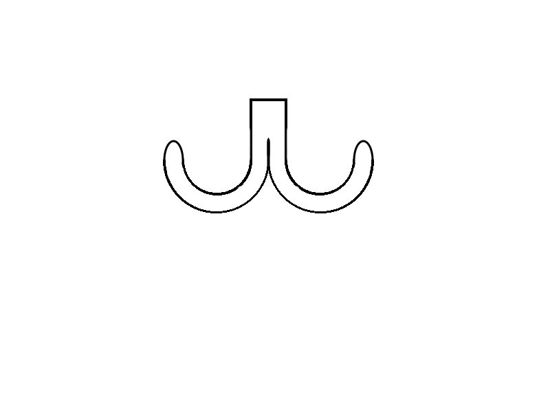
Second, the sides of the profile are mostly flat, which couldn't be done by removing material from a circular profile. You'd have to add material back to fill in the curves. So that's a non-starter IMO.

Today, you could do it with a very small (say 1/16") ball-nose on a CNC mill, doing multiple passes to carve out that profile. Very efficient. But in 1966, forget it.

So the more I've thought about the milling and casting ideas, the more doubts about them I've come up with. Just the opposite with the bent strip idea -- the more I think about it, the more good reasons for it I can think of. It's fast, requires only a bench vise and some hand tools (and possibly a quick trip to the bandsaw), and gets it done. Crude, but that's par for the course with phasers. And it creates the profile we see as a natural byproduct of the method, as opposed to time-consuming reshaping for no good reason.

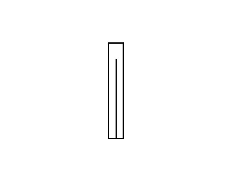
Something I'd forgotten about: This profile was in Matt Jeffries' drawings. Look at section B-B here, on the left side of the page:

Jefferies%20Notes%20001.jpg


So now we'd also have to think up a reason they would start by milling out a round profile and then do extra work (for four heroes) to get to the designed shape, when bending it would be very easy.

There hasn't been a phaser detail debate like this in years, it's deja vu all over again :cool And though I'm still skeptical, I'm starting to lean a bit closer to this at least being possible.
As well you should be skeptical. We all should be about all our certainties when it comes to props we've never inspected ourselves.

For instance, I'm skeptical about the milling + filing theory, but I can't say it's impossible. ;)
 
Last edited:
I was about to post the Jefferies drawing, it certainly matches the final piece which suggests it was designed and made not a found item.
 
Didn't the real side turn have ball catches that allowed it to rotate and click into place? But it has since become solid? I'd be very curious to see an attempt made at recreating it via the 'bending' method. I'm certain that 'triangle' is nothing more than a spec of dirt, but that wouldn't discount it possibly being made from a bent piece and I look forward to seeing the results.
 
There hasn't been a phaser detail debate like this in years, it's deja vu all over again :cool And though I'm still skeptical, I'm starting to lean a bit closer to this at least being possible.
This is big:eek especially after years of images from every angle..Kinda excited.
 
Didn't the real side turn have ball catches that allowed it to rotate and click into place? But it has since become solid? I'd be very curious to see an attempt made at recreating it via the 'bending' method. I'm certain that 'triangle' is nothing more than a spec of dirt, but that wouldn't discount it possibly being made from a bent piece and I look forward to seeing the results.
The MJ drawing does call out a "click stop," but there's more than one way to do that. Also, in the phaser autopsy video, starting at 3:26, the dial is shown turning, and the guy handling it says "It even clicks." So they did put in that feature, but no one knows how -- the whole reason we have this doubt is that the whole dial is covered up in back.

Now, after all this, I'm not averse to doing the old ball-bearing trick. But it can also be done with a little selector switch.


Last edited by a moderator:
Thanks for clarifying. Ok, I see the split strip concept. I see some challenges in fabricating it this way, but I can't disprove the theory. I get the feeling that some time with a needle file set on a rod could have done this if need be. But perhaps it was a split strip. It'll be fun to see where this goes.
 
Thanks for clarifying. Ok, I see the split strip concept. I see some challenges in fabricating it this way, but I can't disprove the theory. I get the feeling that some time with a needle file set on a rod could have done this if need be. But perhaps it was a split strip. It'll be fun to see where this goes.
That's kinda where I am, but leaning toward the strip. I know I can make it that way, but the question is whether it's quicker for an experienced propmaker than doing the end of a rod with files and a rotary tool (which they certainly would have had). Not being one of those myself, that's hard for me to test for.

It's also possible to use a rotary tool (whatever "Dremels" were called back then) with a disk grinder bit. If the profile of the bit is really narrow but still curved, you could pull this off -- and I certainly can't disprove that, either. You could take a few inches of your 1/2" rod, have the tool on your bench vise, make the cuts on the end, and then part it off on a lathe or bandsaw.

So here I am blowing fog over my favorite theory -- not something I'd ever do in front of opposing counsel. :p
 
So here I am blowing fog over my favorite theory -- not something I'd ever do in front of opposing counsel.

I should hope you're in safe company.

I suppose I'm the most curious how the split strip could consistently be made so perfectly round sitting in it's tube housing.
Also, the method for cutting the strip would have to be super razor saw thin or there'd be a nasty squared artifact in your triangle.
 
This thread is more than 5 years old.

Your message may be considered spam for the following reasons:

  1. This thread hasn't been active in some time. A new post in this thread might not contribute constructively to this discussion after so long.
If you wish to reply despite these issues, check the box below before replying.
Be aware that malicious compliance may result in more severe penalties.
Back
Top