TOS ENTERPRISE Cutaway

strengthof10men

Active Member
Hi . This is the first time posting on the scale model section of therpf. I have always loved star trek and when I found out that there was a cutaway model I had to have one. I have only previously assembled models and painted them. But have never put any electronics into them. So I had to learn a little about electronics even before I started. I was coming from the no knowledge of electronics basically believing magic imps lived in my television and made the pretty pictures happen. To soldering up kit circuits.


I have seen people tackle this model on other websites. But when they have done it they complete it was a sealed model. I wanted it to still be a cutaway. With the cutaway sections able to light up when reattached.


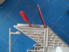
First I need a base to put all the electronics in .


I measured the model so I roughly knew how big it would end up. Then designed my base to be slightly smaller

basea.jpg

I wanted it to look like a combination of the arm rest from the command chair and a wall panel from the enterprise.
basee.jpg

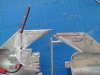
From the same piece of wood I needed to cut out a gasket for the lights and buttons. I then decided to replicate a comm panel for the other side of the panel
comma.jpg

The comm panel would have a section which will light up just like the show.
commd.jpg

I cut a hole to go behind the screen so if I decide to add sound to it in the future I can use it as a sound hole I’m using a piece of white plastic for the light. I wanted to use the original type of grill cloth for the speaker. But it was too expensive, with all the extra parts I was buying for this model I had to start keeping the price down. In stead I used perforated paper and painted it gold. The bottom of the comm is a bigger piece wood so the top can sit on top of it and create a step. Just like the show.

baseg.jpg


The buttons where ‘push to lock’ buttons I found on eBay. These weren’t my first idea for them I went through a lot of trouble to find the right type or style of buttons that the show used. Which were the switches from the inside of freezes that make the light go on and off (spoiler: the light goes off )And I also looked into how I could fake that for a cheaper price by using toggle switch boots, which are rubber protective caps to protect toggle switches from water. But in the end I decided that if I didn’t start this thing I would never get it done.
I couldn’t find the lights I wanted . So I had to make them. I poured clear resin into a water colour mixing pallet and left it over night. I then popped them out. They didn’t all work perfectly so I made more than I need so I would have options. I also needed domes for my bussard collectors so this killed two birds with one stone. I had to be sure to mix and pour the resin outside as the fumes would have been bad for me. I wanted the resin domes to be different colours but I found that by adding colour to them it altered the ratio of resin to catalyst and stropped the resin from setting so in the end I made coloured pieces of plastic so that when the light shines through them they would seem to be the correct colours from the show command chair.


I used canopy glue to glue the resin domes to the gasket because I wanted it to dry clear and not leave that frosting on the plastic that super glue does.


buttonpanela.jpg

I then cut five rectangle out of acrylic and used a label printing machine to print out descriptions for my buttons. I stuck the labels on the acrylic and the acrylic to the gasket.

basek.jpg

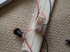
drill a hole later for the wires to come up through and a tube.

you can see it all work in the video below

USS Enterprise TOS model base - YouTube
 
This is the part I had to study for. i may be wrong about all this but i'm only going to learn by trying


I bought a reel of warm white led strips of eBay. They where 12 volts.
I then bought a kit for navigation lights for a RC helecopter, that was 4V
I bought two kits for a led chaser circuit. That was 4v - 6v
And self blinking leds 4v


But I wanted to run them all from one adaptor. So you can see the problem . If I run the 12v through the 4v navigation lights im going to burn them out. I could have avoided all this if I only used individual leds instead of the led strips. , but I was new to all this. I consider it a hard lesson learned. But it also forced me to think about solutions. And problem solving is part of the fun .


I came up with some solutions. A could use a transformer to make a power drop . I could make a voltage regulator or buy one or I could used relays to switch to a different circuit that runs of a smaller voltage battery. At first I bought a ‘step down buck’ form eBay. This is a voltage regulator , this means that you can have 12v coming into , but set it so that you have less volts coming out at a constant rate , such as 5v. The one I bought from eBay was faulty , I shouldn’t have been surprised as it was so cheap, but I couldn’t keep spending money like this. I was also worried that the voltage regulator would causee the base to heat up to a dangerous level . As it basically burns off electrons turning them into heat to get rid of volts. I turned instead to two relays that I had. I bought these as part of my self taught study of electronics. I had bought a book and was trying to go through it one page at a time . Buying the parts it mentioned and trying to make the things it suggested. I admit its not going well I have a memory like a fish. And im still not entirely sure electrically isn’t just wizardly .


I should explain the switches and what they would be hooked up to in order for you to understand what im talking about.


Switches:
Alert button : just makes a 12v light come one . that’s it.
Life support: this button turns on the 12v led light strips which will illuminate the interior of the ship.
Nav lights: turns on a 12v light strip . Triggers the relay which then turns on the 4v nav lights.
Warp: turns on a 12v light strip . Triggers relay which then turns on 6v chaser light circuit.
Hail: turns on a 12v light strip

ledstripbuttons.jpg

This is the inside of the base , the part that will light up the resin domes when you press the buttons. I am using foil tape to bounce the light around.


I then bought helicopter RC navigation lights from Amazon

It had more lights than I need so I kept four and pulled the others of f. you also get a lot of wire with this so I cut it down and re-soldered the led’s back on . I kept the wire as it might come in handy later.
I connected the 12v adapter to the relay and then connected the relay to the battery pack and the navigation lights.


You can see my test fit and a better explanation in the video below. Please excuse my dreadful speaking voice.

https://www.youtube.com/watch?v=UZNudbGpuAg&feature=youtu.be
 

Attachments

  • neckconectiona.jpg
    neckconectiona.jpg
    162.5 KB · Views: 112
  • neckconnectionb.jpg
    neckconnectionb.jpg
    170.7 KB · Views: 88
  • relaya.jpg
    relaya.jpg
    198.2 KB · Views: 82
The wires from the relay had to travel up through a hole in the neck and saucer which I drilled out using my rotary tool (Dremel). You can see the configuration in the photos . I have since change the wires to a smaller gauge but the idea is still the same

neckconectiona.jpg

neckconnectionb.jpg

I then soldered the wires to the nav light control box and hot glued it in place.
Because I want the saucer section to brake away so you can see the interior but also I want the lights to continue to blink on and off on both halves the circuit is in parallel. I cut one of the led wires and stripped them. I then stuck foil tape on the saucer section at certain points and connected the wire to them simply by taping more foil tape over the top of them . On the other side of the dist I did the same thing. Now when the two halves are connected all the lights blink on. But when the saucer section is halved , the lights in the main section continue to blink. As you can see in my video.

https://www.youtube.com/watch?v=fbstCvfQiag

navlightsb.jpg

In the video you will also notice that the impuse engines pulse on and off. I know this isn’t how they look on the ‘real’ enterprise , but I enjoyed the way it looked so I kept in instead of just having static lights.
 
Bussard chaser circuits.


I found a chaser circuit while looking on you tube for bussard lights. I know there is already kits out there for this. But I was trying to be cheap. I bought two of these kits from CONRAD and soldered them together. This was the first time I had soldered a kit. To my annoyance the instructions are in german” arrgh! So I took a picture of every page and used google translation app to translate it into English for me. Its isn’t perfect but it gets the job done. If anyone would like to buy the kit but couldn’t be bothered to translate it like I did , just ask and I will post the translation here for you. Its about nine pages . There is also a circuit diagram so if you just want that I can scan it in and post it for you.

circuita.jpg

The down side was that the capacitor in the kit was different to the one depicted o the package. And I wasn't sure which way round to place it. I searched for quite a while on google images untill I found a similar one then found out that it didn’t matter. D’oh . Still better to be safe . Also never touch the integrated circuits (the chips) with your fingers as even static can be enough to break them. If you have to touch them ground yourself first by touching some metal pipes to discharge the static.

video:
https://www.youtube.com/watch?v=sp3jWQIVPEI
 
The chaser kits run of a battery which is triggered by a relay just like the nav lights are.


The legs of the led’s were then pushed through the holes in a disk I made from a bit of plastic and soldered on the other side. Careful notice was taken to the order the leds went in as if they flash in the wrong order, there is no point in doing it in the first place
bussardledsa.jpg

bussardledsb.jpg

This is the part which is just an experiment and as of typing this I don’t know if it will work. But I just went for it . Because I wanted a brake away section the wires which flash the leds on the bussard collector had to stop at the hull . They then have to connect to the brake away section and travel up the nacelle pylon into the nacelle. I ground out some of the material in the pylon first to make room.


I soldered the heads of tacks onto the wires and drilled out holes in the hull and pushed them through. I then glued them in place. I would love to tell toy that it was easy but I screwed it up so badly that I had to cut it all out and start again. There isn’t a lot of room inside this thing and things can got wrong fast. I even melted some of the plastic with the soldering iron. I also burnt my self but I was more annoyed at damaging the model.


This break away section will also need to have warm leds to mimic interior lighting and a strobe light.

testfitstrongback.jpg

wiresinteriorb.jpg

nacellewireupd.jpg

I had to come up with a way to make the two parts connect . I ended up covering one side in plastic film . The kind you wrap sandwiches in and pressing Milliput (a two part putty) into it to get an impression. I then pushed the wires through it. In hind sight I would have just used magnets . But that only something I learned after I screwed up. More on magnets later.

nacelleconnectiona.jpg

In order to connect the warm led strip and the self blinking led strobe. I had to make more contact points. I wont bore you with the three failed attempts that I spent weeks trying out and just show you the idea that works. Simple turned out to be better. , I will tell you however that despite what you would believe you can solder to nickel covered magnets. You just have use flux and be fast so as to not demagnetise the magnet with the heat.


On the backside to the interior piece I drilled out four holes. Two for the positive and negative for the led strip and two for the positive and negative for the strobe light. Again all the circuits where wired in parallel so the circuit could be broken and the rest of it would still function. I soldered the wire to strips of copper or maybe it was brass that o got from paper fasteners

pins.jpg

On the other side . I cut holes in a piece of plastic and made a connecting plate for the other side of the circuit. So now when the two sides touch , the lights come on.
The other nacelle was easy in comparison I just ran the wires through after I ground out some of the material in the pylon first to make room. As you can see from the picture the leds appear to come out of the interior of the nacelle tube (I haven’t explained that very well but when explaining the inside of fictional space craft I don’t always have the skills to describe what’s going on. But fortunate that’s what cameras are for.

nacellewireupf.jpg

To get this to happen you cut out a hole in the back of the nacelle interior detail and cut out a slot as shown
nacellewireupa.jpg

You then feed the wires through the slot and through a slot you have also cut in the bracket section that attaches the nacelle to the pylon.
nacellewireupc.jpg

nacellewireupe.jpg

If your still reading this and feeling exhausted , you are not alone and I’m not even finished yet.


On the front of the ship. Up at the deflector dish end there is also a break away section which needs to have interior warm lights. I accomplished this the same way . I apologies that I don’t have photos of this section except for one. In this photo you can see one of the wires which lead to a bit of brass . This will connect to the brake away section and complete the circuit . I will take more pictures of this section as I come to complete it.
frontlightswires.jpg
 
Extra parts!


It brakes apart, It’s a cutaway model so I assumed that you would get model parts for both halfs right? Wrong. Only the biggest part of the model gets the interior kit parts. The sections that break away get none. I didn't like this so I decided I would have to make my own. I decided that I would make an extra saucer section cross section and an extra interior of the warp nacelle.


To do this I flipped over the interior deck section and made a silicone mould of it then cast it . I did the same for the warp nacelle. If it seems like i've glossed over how to do this part even though it sounds complicated there is a reason. I have made a video of it instead! Not only does it show you what I did, but you can use it to learn how to cast other model parts as well.

part one
https://www.youtube.com/watch?v=hs3pbTApo5s

and part two

https://www.youtube.com/watch?v=marL6DGYPr0

DON'T RECAST OTHER PEOPLES STUFF! i was only making spare parts for my own model which i needed and will never make any more to sell or give away.

deckmoldsa.jpg

I want the deck section to be back lighted so I disposed of the original kit part and cut my own out of thin white plastic sheet.

deckinsert.jpg

I also need another decal for the other side so I scanned in the decals . Flipped the image and printed out a second copy which I would print on photo paper and glue onto the plastic. And behind the new deck section.
 
Magnets!


I was having trouble finding a way to attach the cutaway section to the model. They tended to want to fall off, especially with all the extra weight that I added to them with lights and wires. I tried drilling tiny holes and inserting rods into the other section . But this became a problem with the space I needed to use. I ended up buying small magnets of eBay. I had two types. Small cubes and small rods. I have decided that the rods work best as with the cubes there are naturally six sides so its easy to confuse the polarity and that sucks when you glue them in backwards and the two halves repel each other. So I stuck to using rods. There are four on the back part. Two in the hanger bay and two up by the top of the main body of the ship.


There are also two magnets soldered onto wires in the front section which will connect the LED circuit when those two halves are connected


You can see how this works in the video below
https://www.youtube.com/watch?v=2jTfaKnrXsE

Next I am trying to fix all the gaps in the ship with Revell modelling putty. As I had distorted the shape when glueing it all together I have to sculpt it back into shape. Im disappointed in my self that I let this happen as I know the ship will not be perfect. But I quess that’s another lesson I learnt. You can see yellow putty already on the model, that is a product called Milliput .


I have now filled alll the gaps in the saucer section but found that the two halves don’t want to go back together flush. As of yet im not sure what to do about this. It would be a shame to have to break both halves open to refit the deck floor sections.


Im getting a bit burnt out on this project as ive been doing it on my weekends since Christmas and it still isn’t finished. I may have to take a brake and use that time to think about paint and attaching the wires to the base. I will have to paint it first as once I start attaching wires to the base I have committed myself to that course of action and I would dread having to desolder it all because I forgot to do something that I cant get to once its in position


I have bought Tamiya F.N Grey paint for the hull as this is the colour that other websites suggested was the closet match to the original model. I have done a test and although it may be the right colour, it isn’t the right colour for me. I want the ship to look how it did when lit up on screen and not how the model looked in real life. With this in mind im going to use tamiya pearl white with a white base. So if anyone out there has any advise on how best to use this please let me know. Im assuming that I have to primer it in the colour that I want to shine through the pearly coat. but do I put the pearl coat on before or after I put o the transfers?
 
To take a break from electronics I thought I would paint something, which is the part i enjoy the most. I decided to paint the bridge section which is a self contained part and i could play with it without worrying about how it fitted with the rest of the model. When I broke it off the sprue I noticed that it doesn't have the railings like the bridge has on the show.

I took a piece of scrap plastic and cut some out with a knife, then glued and painted it with a tooth pick as i didn't have a brush small enough

bridgeb.jpgbridgec.jpgbridged.jpgbridgee.jpg
 
Bussard domes


Bussard collectors . The model only came with two clear plastic domes for the bussard collectors but I needed an inner dome. I made these by wiping mould release into a water colour paint mixing pallet and pouring clear resin into it. I waited for it to dry. I then popped them out. Then I put on silver grey stickers that I got from HobbyCraft

bussarddomesa.jpgbussarddomesb.jpg

The bridge


The bridge doesn’t come with hand rails and I couldn’t live without them so I made my own. I took some plastic sheet and using a craft knife I cut them out. It was harder than it sounds because of how small they have to be. You can see what I mean by looking at the pictures below

bridgeb.jpgbridged.jpgbridgee.jpg


Stand.


I had planned on just having a pole as the stand. But I decided that I wanted more stability just in case someone knocked into it. I found a cone that I liked the shape of. It came from a Lenore detergent bottle. I made foam core disks to stack up inside it.

standa.jpgstandb.jpg
 
TOS ENTERPRISE Cutaway finished

Finished.


I have finished my Enterprise but it didn't all go according to my plans. The break away section on the neck works just fine as well as the starboard nacelle but my plan to have the port nacelle be attachable and have the lights come on failed. I just couldn't get a decent connection , it upset me but I had to admit defeat.


When I assembled the model I printed out my own deck decals and glued them on. It seemed easier than painting something this small. I even added a bowling alley!


When looking at the hanger bay I decided it looked a little empty so I also made a shuttle craft.

finifront.jpgfininacelle.jpgfiniport.jpgfiniportb.jpgfiniporte.jpgfinistarboard.jpgfinitop.jpgfinitopb.jpgfinitopdome.jpg
 
This thread is more than 9 years old.

Your message may be considered spam for the following reasons:

  1. This thread hasn't been active in some time. A new post in this thread might not contribute constructively to this discussion after so long.
If you wish to reply despite these issues, check the box below before replying.
Be aware that malicious compliance may result in more severe penalties.
Back
Top