Team Fortress 2 Heavy Minigun Build (3D printed, IMAGE HEAVY)

I decided to design and print some cool TF2 tokens to hand out to cool people at con when I'm suited up as the Heavy.
Multicolored and plain white.
I got the idea from a really great Jack Frost last year who gave my girls snowflakes after taking a picture with them. :)
 
love the chip idea; didnt have a jack frost do it for me, but had a danny ocean (actually really cool to see in person) hand out home made casino chips.
 
UPDATE


I got the bullets painted and assembled for my bandolier. I will begin assembling the structure out of black vinyl soon.


Aluminum sheet applied to the ammo can (7-up cooler)
Edges of all aluminum sheet to be packed with bondo and sanded/blended to cooler body for smooth transition and uniform appearance


Inside edge secured with adhesive, body wrapped, then final lip folded and riveted with intentional uneven spacing (authentic appearance compared to game)


Positions of holes marked from inside with punch for drilling/cutting (I'll do this before Bondo and paint)
 
UPDATE


Okay, it was time to build the back half of the lower assembly (behind the ammo drum).
I found a 12" concrete form tube with the ID exactly the same size as the OD of the 7-up cooler lid!


I used small blocks (with screws and shoe goo) to secure the cooler lid to the concrete form tube on one end... the other end was fabricated from 11/32" plywood. The rectangular hole will be my access hole for installing electronics, running wiring, and changing the batteries. I'll design and 3D print a panel to cover the hole with switches and volume pot... very similar to the switch console you see on the actual minigun in the game. :)
The 3 holes you see drilled in the lid are one each for Motors, Lights, and Speaker.


The underside of the rear cylinder has a block into which the tube leading to the front is installed. I'm hoping to use the flat surface of this block to rest the gun... we'll see. Anyway, it's made from plywood and covered in aluminum sheeting.


Attaching the front and rear cylinders can't be permanent... just in case I need to service the motors, belts, or speaker. So, I installed 3/16" threaded Tees and will use 3/16" bolts to fasten the two halves together.


It seems I'm dressing everything up in aluminum sheeting... it's lightweight and provides a nice, smooth surface for painting.


I'm currently in the middle of Bondo and paint... front can is primed and ready for more sanding and filling as necessary. Rear can is Bondo'd and ready for sanding... hopefully, it will just turn out great and I can get it all painted.


I'm getting very close... I can smell it! :)
 
UPDATE


I printed the back panel for the switches and access hatch, but forgot to take any photos. :(
I'll take some photos later.


But I do have photos of...


Fake hex-head fasteners for the handle's "Y" section


Brass eject cover (yes windows are unevenly spaced, and yes the back is curved for flush fit to rear can)


Front pipe elbow and end cap (elbow is actually a PVC elbow with printed flanges... needs to be strong)


That is all for now. :)
 
UPDATE!


Okay, I got a few things done this weekend.
- lots of painting done
- BANDOLIER DONE! (except for glue to secure shells)


Rear Can painted


Rear Can Hatch (with 2 holes... main power switch and volume control knob)

Tabs are secured with JB Qwik and screws... not going anywhere
This will be held by a 3/16" thumbscrew... to allow servicing of electronics and change of battery


Ammo Can Nipple


Brass Eject Port Cover and Ammo Can Nipple Ring (nipple ring?)


Ammo Can


Paint drying on pieces


Bandolier is done
Made from black vinyl
Stitched front side longer than back side (to make rounds more pronounced toward the front side and lay flatter on the back side)


Next steps:
- design and print control box (for right hand, hard mounted to frame for access to on/off, firing, and sound switches)
- final touch-up and paint of main components (before assembly)
- begin assembly :)
 
Serious business man! I am so impressed with your hardwork and dedication to authenticity! Way to problem solve and find solutions!

Seriously inspiring.

Thanks,

Tank
 
Thank you for the kind words. :)
Tonight, I got step 1 of the assembly done (front can nipple and ring installed AND front can to handle assembly INCLUDING cosmetic side brackets)... pics coming tomorrow. ;)
 
UPDATE


Okay, last night I had some time to perform some assembly...
- Cosmetic Brackets added to white Ammo Can
- Handle Assembly and Bearing Holder portion of Barrel Assembly assembled with Ammo Can
- Ammo Can Nipple and Ring installed


Cosmetic Brackets attached with Shoe Goo for flexibility during installation


Cosmetic Brackets wouldn't be complete without Cosmetic Screwheads


Completed Handle Assembly (white "Y" portion will come off and be further finished when I build the rear Handle Assembly)


Ammo Can, Bearing Holder, and Handle Assembly


Ammo Can Nipple (I attached a layer of felt to the base of the Nipple to keep it from potentially rattling when the speaker is operating)


Progress to date


Next steps:
- Install rotating Barrel and belts
- Install Motor Bracket
- Test finished Barrel + Motors Assembly
 
UPDDATE
(before you get too excited, I've got to remove the barrel and replace the 3 belts with shorter ones... the ones I installed were about 2" too long)


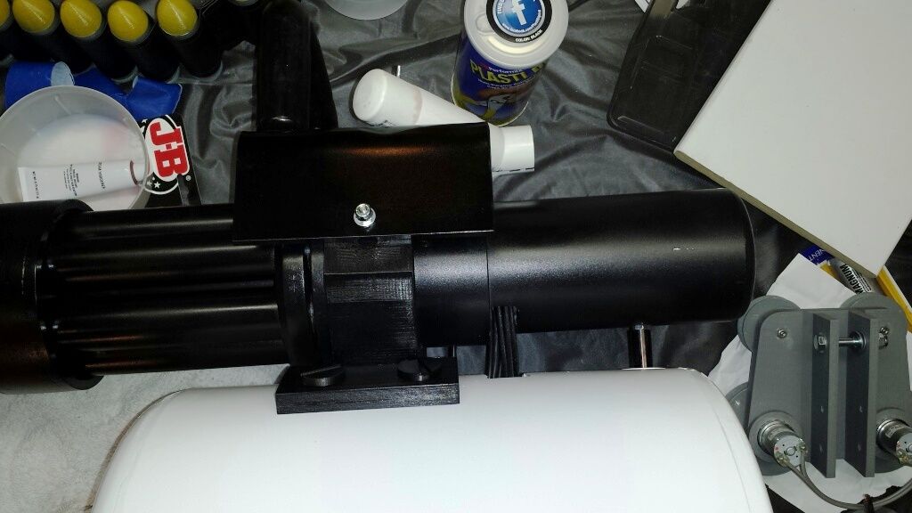
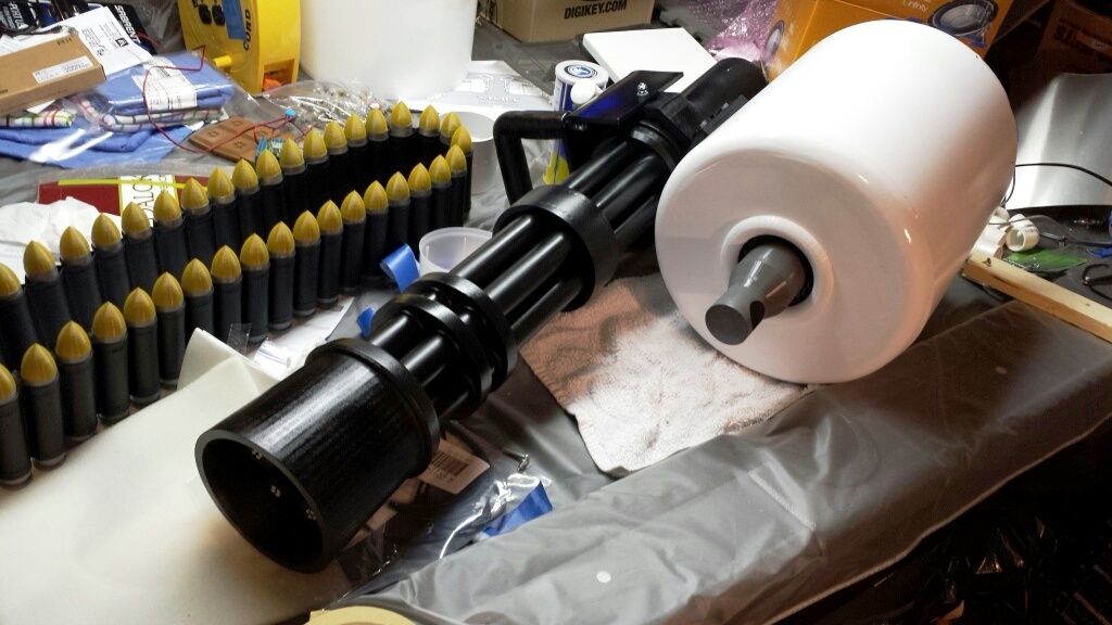
I installed the Rotating Barrel and Belts


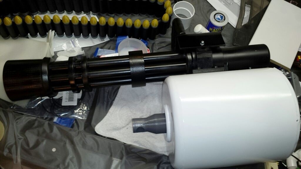
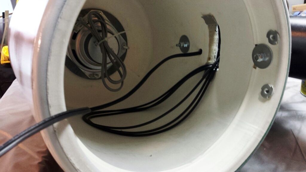
Belts and LED lead enter here...


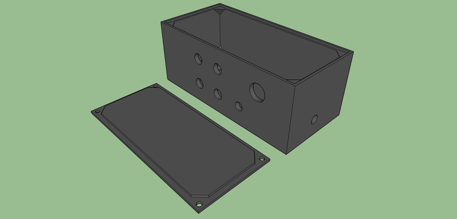
Another part of this project I had to tackle was how to control the lights and motors and sounds.
I've wrestled with how to do this effectively without ruining the appearance of the prop.
The solution I'm using is to make a custom control box for my right hand (near the rear of the prop, attached to the rear "handle") to work everything.
This box will be against my right hip between the rear frame and my body... fairly hidden, but accessible.
It shouldn't show up in photos or detract from the appearance of the finished prop.
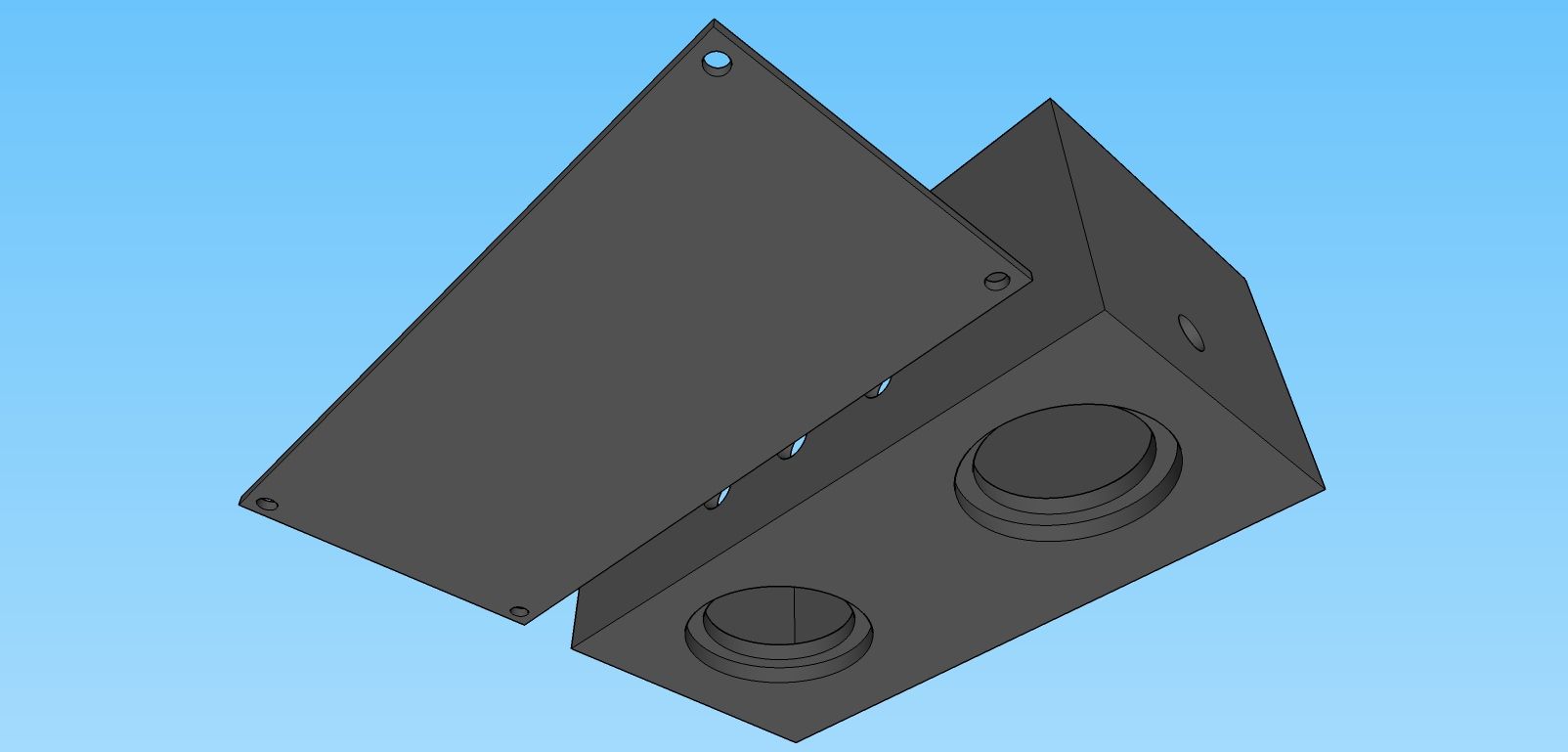
I will attach it using JB Qwik around both registered fit holes and ONE bolt + fender washer (or small bar) to hold it flush against the frame, so it won't break free from stresses of use.
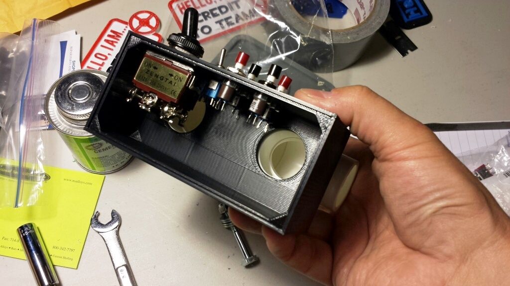
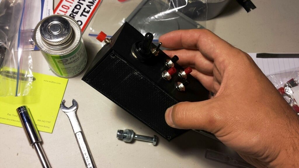
Anyway, here it is...


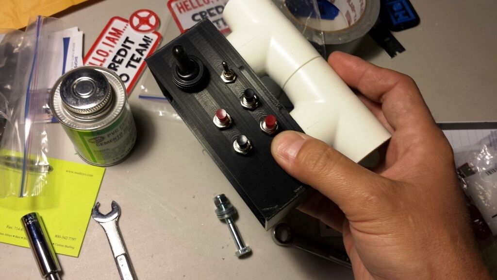
The switches work as follows:
- large toggle (black) - engage/disengage motors + wind up/wind down sounds
- red switch on front end - engage/disengage LEDs + firing/spinning sounds
- small toggle (silver) - select firing sound (standard or crits)
- 4 smaller pushbuttons (red and black) - trigger other sound effects


Next steps:
- replace belts with shorter ones
- final test of motors and LEDs
- button up front and back cans
 
This thread is more than 8 years old.

Your message may be considered spam for the following reasons:

  1. This thread hasn't been active in some time. A new post in this thread might not contribute constructively to this discussion after so long.
If you wish to reply despite these issues, check the box below before replying.
Be aware that malicious compliance may result in more severe penalties.
Back
Top