The Nylon Gag MK2 F1 Magneto Skimmer

Evening my friends,

Thank you so much for the kind words, it really means a lot

Well, this week I had some good news and some bad news
Good news is that after two years of working only four days a week we are now back on five days :D
Bad news is that I have lost my Friday modelling day, 8 hours of solid bench time :(

But at least I have a job, which in this area at the moment is a very good thing.

Enough waffel, mmmmmmm waffels, on with the update,

Lots of head scratching and thinking, not so much build progress, this really is one piece after another,
my lights still haven't arrived yet :angry so it is a bit of a hold up as far as the engines are concerned but anyhoo's your daddy,

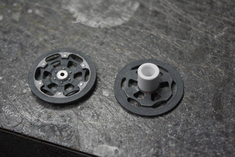
Used these MotoGP front disc brakes for more internal details that you won't be able to see, obviously,


Picture%2520084.jpg


Decided i didn't like the baby bottle caps because they hid to much of the insides and looked to out of scale, had a quick rethink and came up with this.


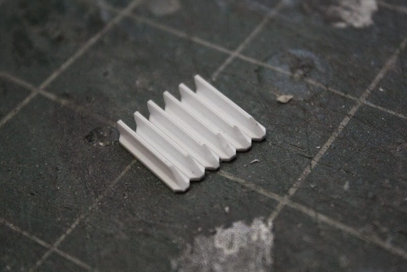
'T' shaped styrene with a taper on one end


Picture%2520085.jpg


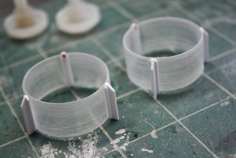
Cleaned up the bottom of the bottles that I cut off and found two wochesteshire sauce pouring spouts
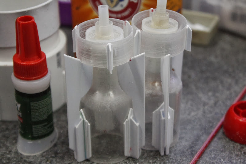


Picture%2520086.jpg


Added the 'T' stock


Picture%2520087.jpg


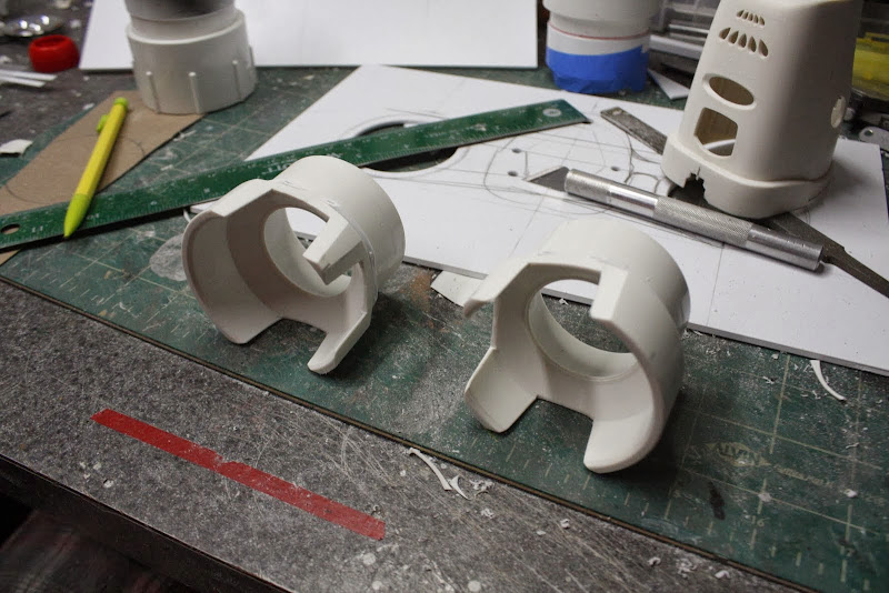
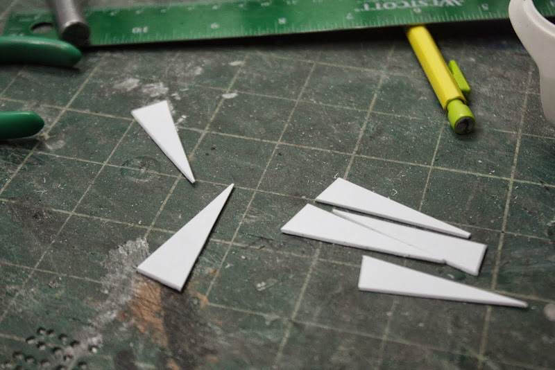
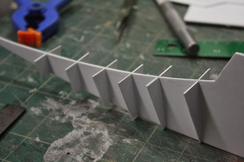
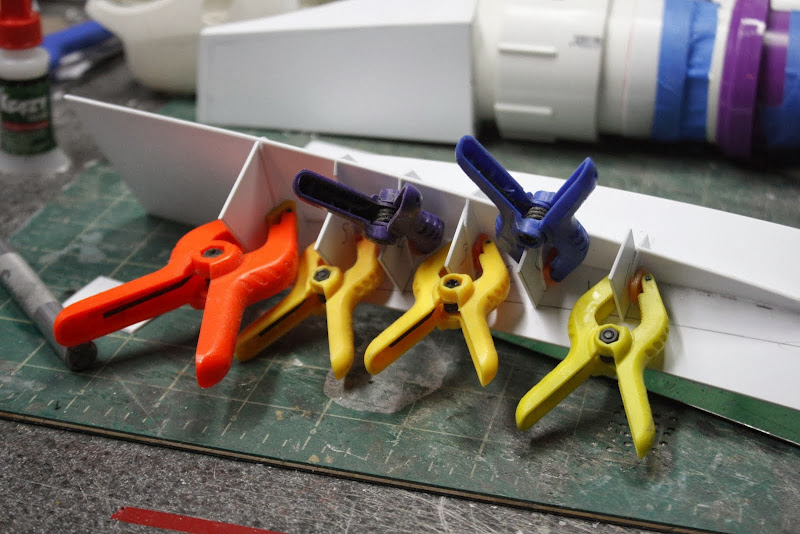
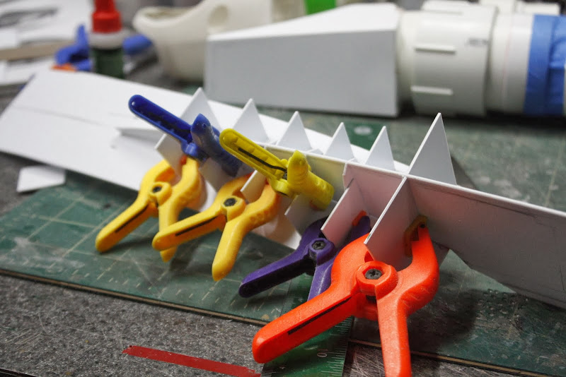
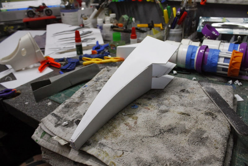
Cut and shaped six thruster vanes and noched them to take the ring,


Picture%2520088.jpg


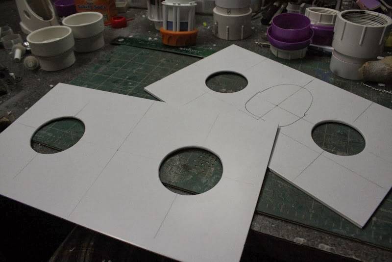
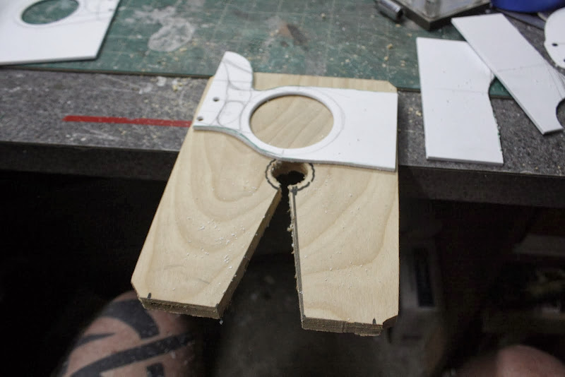
Moved on to the internal frame structure, cut two holes in 3.5mm sheet styrene, the distance between the centers has since changed, plus iI broke my Olfa hole cutter in the process so i had to use the dremel instead, not as accurate but way more fun.


Picture%2520092.jpg


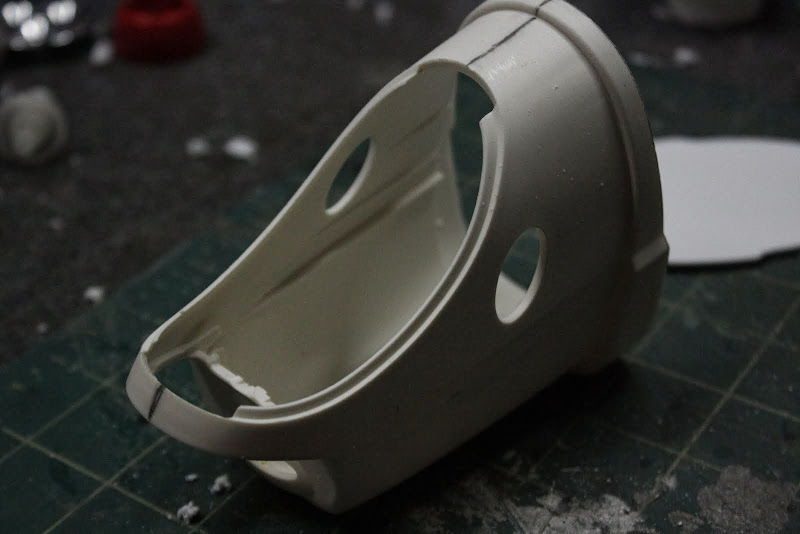
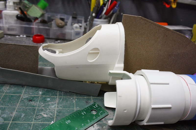
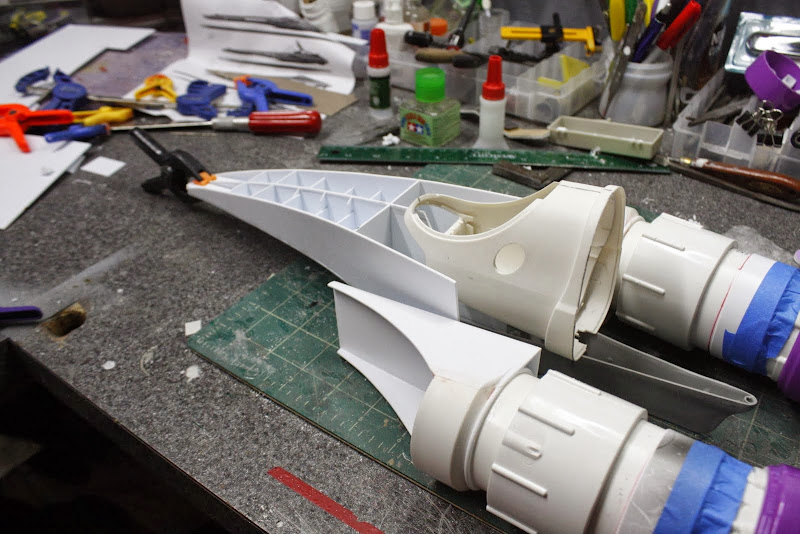
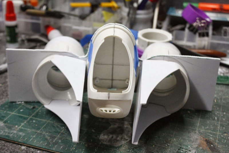
Then I had a mega find, this is one of those desk top air freshener thingy's, where you insert a bottle of cented oil and it heats up and stinks the room out.
Well, after I had cut out all the innards I thought the outer body shape makes a perfect cockpit saftey module
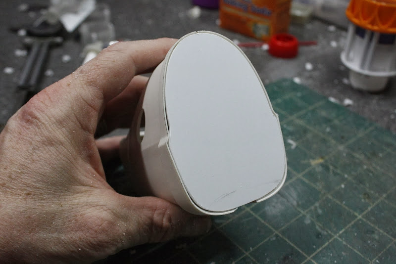

Picture%2520093.jpg


Made a back for it


Picture%2520095.jpg


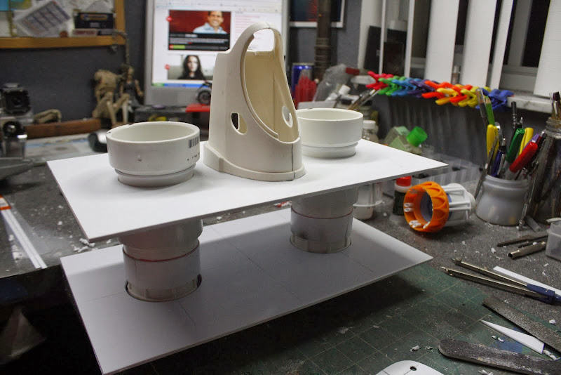
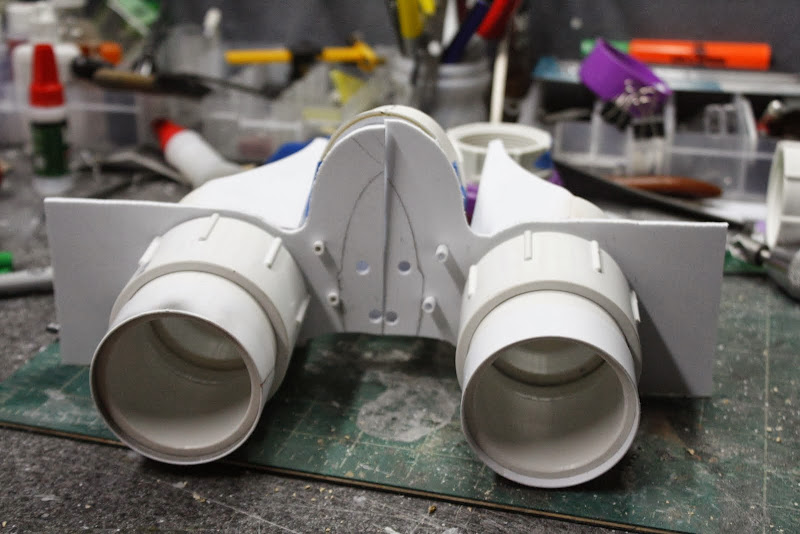
Punched holes for support rods in the internal structure sheets and the back plate


Picture%2520097.jpg


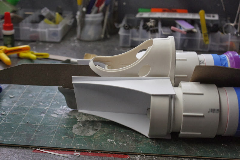
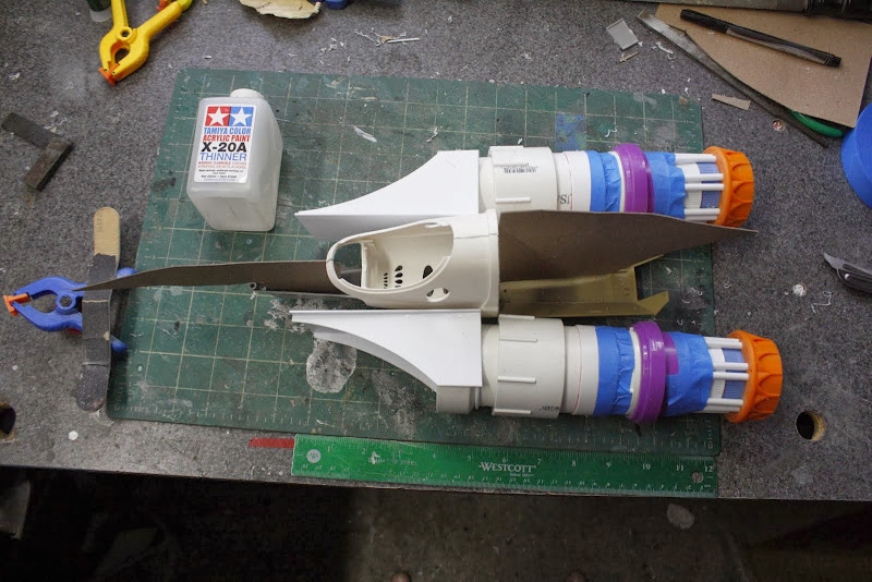
Very very very basic assembly, this is when I decided that the engines were too far apart,


Picture%2520098.jpg


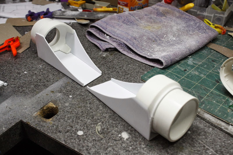
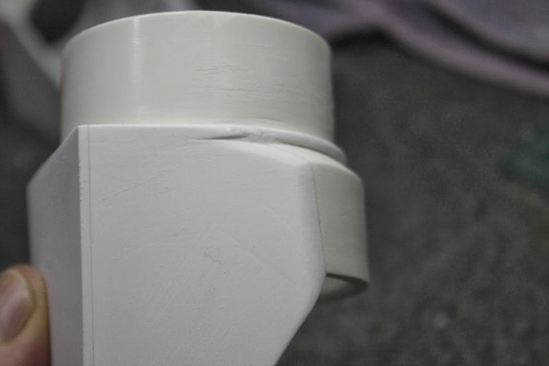
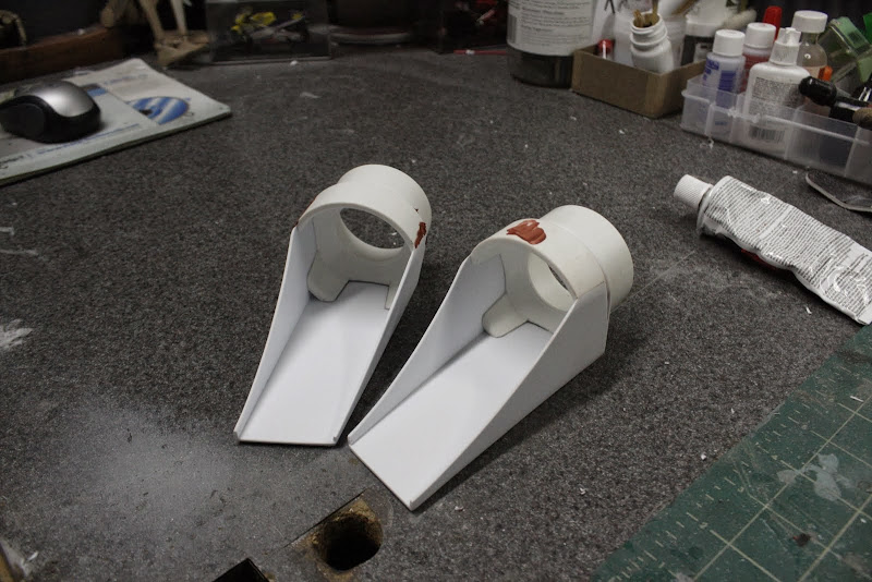
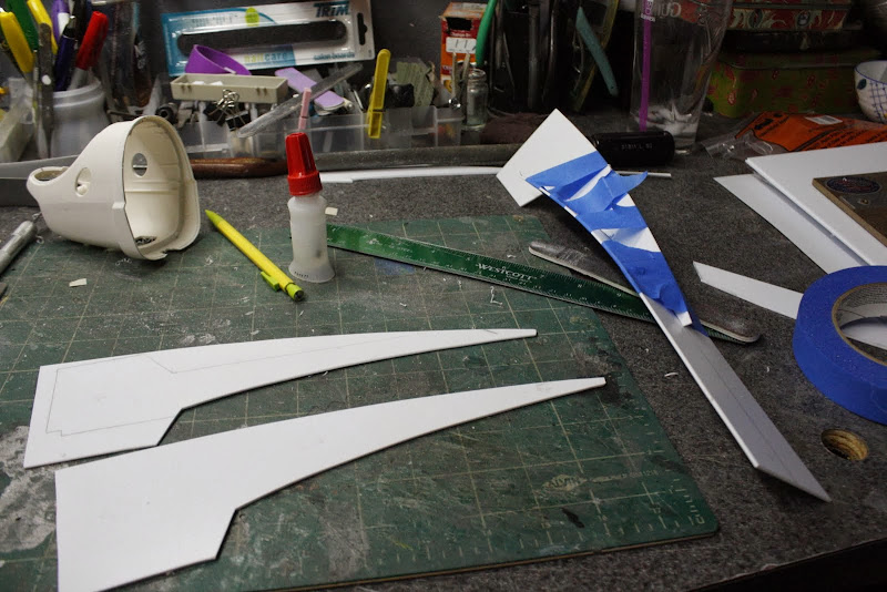
Re-thought the side intakes and did a bit of sanding


Picture%2520102.jpg


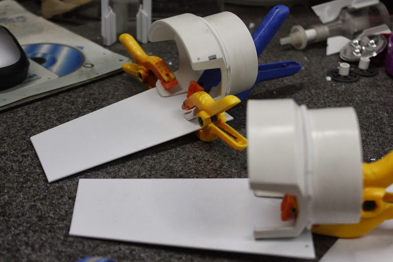
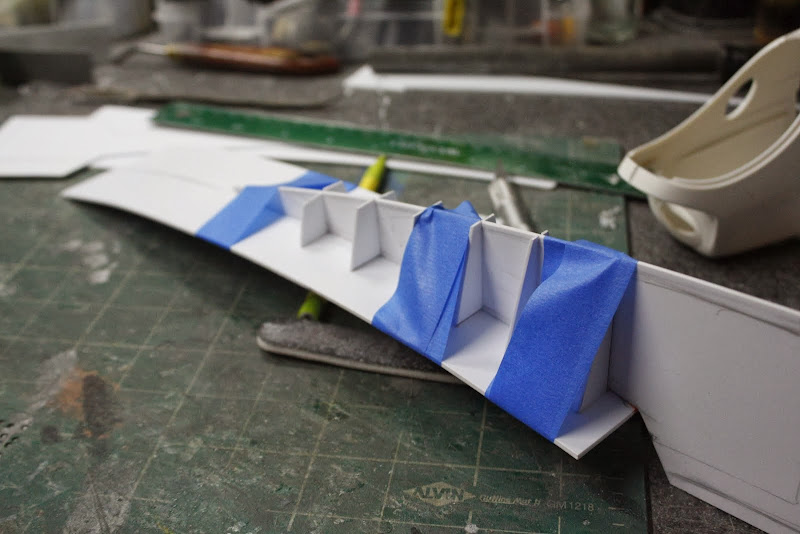
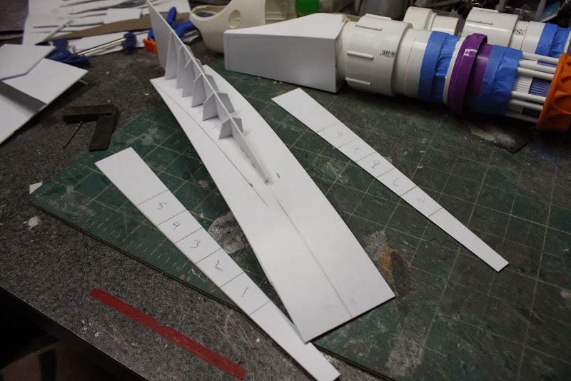
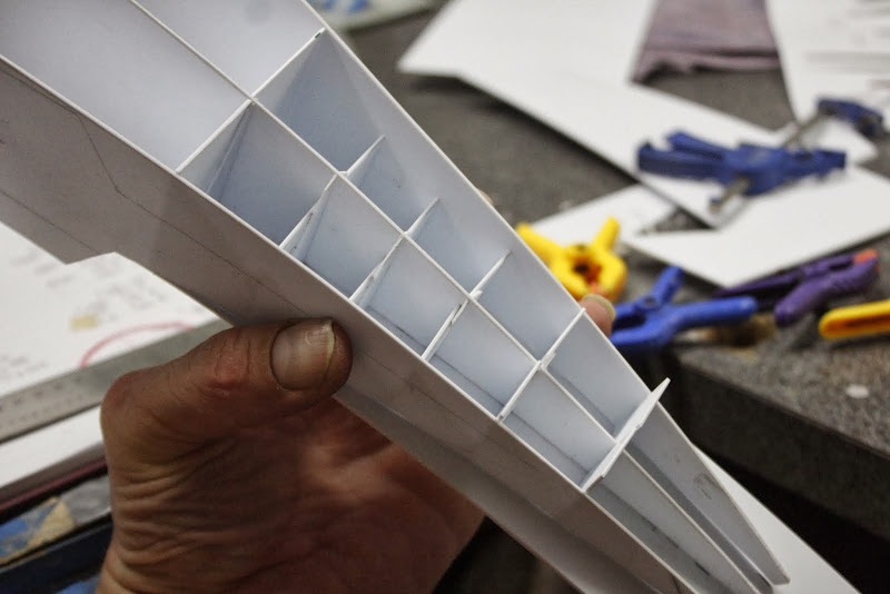
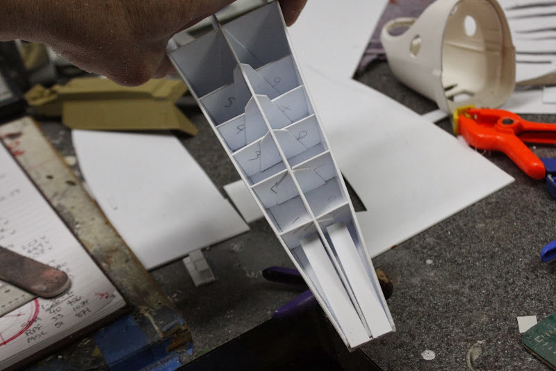
This is the start of the underside structure, a ship hull and a tank hull, perfect


Picture%2520104.jpg


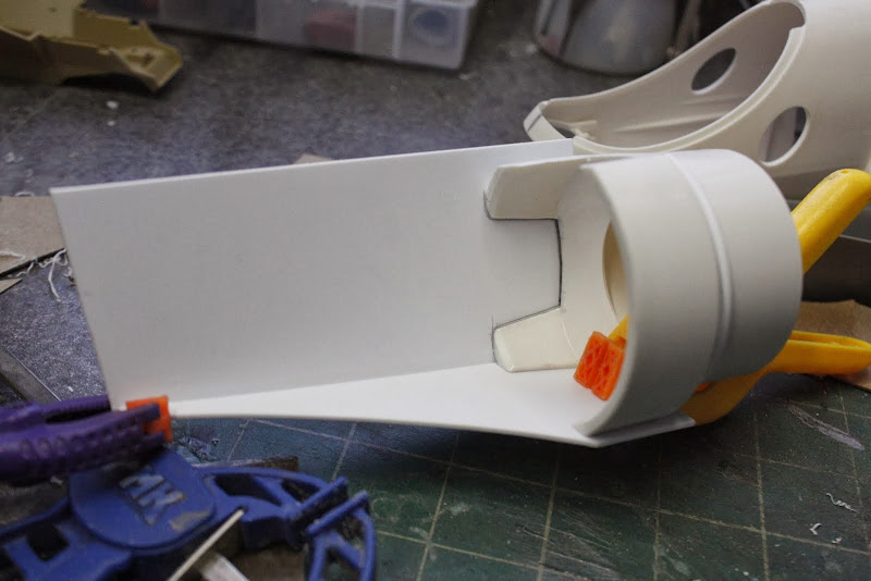
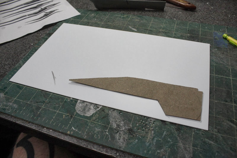
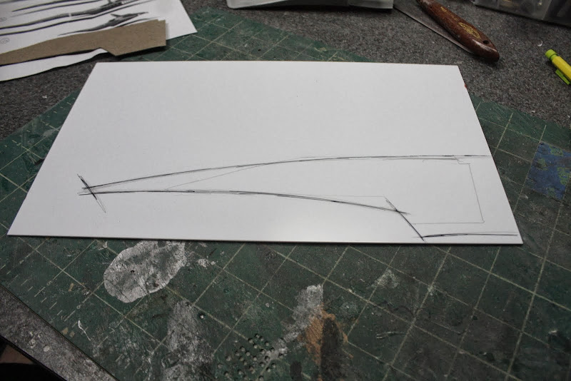
Card board inserts to help me visualize the profile and overall lay out so far


Picture%2520105.jpg


Picture%2520106.jpg


Picture%2520107.jpg


That's all for now

Until next time my friends

Stay tuned and Take care


Gagsterman McGee
 
I love the imagination in your builds, they're the reason I've been hoarding bits, bottle tops, and other associated pieces/parts. You are a definite inspiration.
 
This is already a fun ride! Great to see the updates, and thanks for the 'in step' pictures. They answer so many of my questions...some of them before they even come to mind!
 
Evenin All,
Thanks for stopping by and leaving comments guys, appreciated muchly

Just a quick update this evening on the side pod progress,

Started by gluing 1.5mm styrene sheet to the three flat sides of the modified round side intakes


First the back

Picture%2520108.jpg


Then the bottom with a pre-shaped radius


Picture%2520109.jpg


Then the top, preshaped piece, it's just a fraction larger than the bottom, here you can see it next to the main body mock up

Picture%2520110.jpg


Now I have these sidepod intakes in position, I can more accurately position the ships hull which will become part of the underside 'Tea tray assembly' that you see on modern F1 cars

Picture%2520112.jpg


This top view (with thinners bottle for scale, shows the overall length of the ship, about 22". To keep it relative to a modern car, I think it's going to be 1/12th scale.

Picture%2520113.jpg


I then started cleaning up the outside of the intakes, blending everything together,

Picture%2520115.jpg


Picture%2520117.jpg


Next i will fill these corners to make a smoother transition for the insides


Picture%2520116.jpg


Here's another angle of the whole engine assembly


Picture%2520118.jpg


I may also add some internal details on the intakes, I'm not sure yet, I will see what it all looks like after the corners are blended in.

That's all for now, stay tuned my friends

Take care


Gaggles McGee
 
Loving it so far!!

Looking at the inspiration....

640x336_13669_Ferrari_Gunship_2d_sci_fi_spaceship_rocket_automotive_hovercraft_jet_ferrari_fighter_picture_image_dig.jpg


Are you going for the streamlined look overall or going a little more industrial? With F1 every angle on the cars is for a purpose so I didn't know if you were going to skin things over or keep it more exposed.

Looking Awesome!
 
Loving it so far!!

Looking at the inspiration....

https://lh5.googleusercontent.com/-...aft_jet_ferrari_fighter_picture_image_dig.jpg

Are you going for the streamlined look overall or going a little more industrial? With F1 every angle on the cars is for a purpose so I didn't know if you were going to skin things over or keep it more exposed.

Looking Awesome!


It's true that this picture was my inspiration but i won't be copying it directly.

I intend to put my own spin on it, and interpret where i think F1 will be in the future, sort of setting myself strict rules to adhear to as the Formula does currently.

Also, if you look at the rear of the ship in the picture, I can't understand what all that stuff is for, which for me is a big deal and you are correct that everything is there for a reason and they do look very slick and streamlined, i will be sticking to this concept.

Thanks for the question


Gag
 
Helloooooooo Good evening and Welcome,

Very nice to see the usual suspects along for the ride,
Quick one tonight,


So, hold on tight for a fast ride,
The louder you scream the faster we go

Filled a few ugly bits on the intakes


Picture%2520119.jpg


Traced my nose pattern,

Picture%2520120.jpg


Expanded it a bit

Picture%2520121.jpg


Cut out three

Picture%2520122.jpg


Cut out braces

Picture%2520124.jpg


Glued them on one of the nose profiles following the under side radius

Picture%2520126.jpg


Glued a piece of 1.5mm styrene on to the underside

Picture%2520128.jpg


After it had dryed I removed the tape and cut two tapered spacers

Picture%2520129.jpg


Cut and glued these on both sides

Picture%2520130.jpg


Picture%2520131.jpg


Attached two other two sides

Picture%2520132.jpg


Fixed the nose section with two pieces of rectangle, not sure why but it seemed like a good idea

Picture%2520134.jpg


All the clamps removed

Picture%2520137.jpg


Very rough sanded

Picture%2520140.jpg


Picture%2520143.jpg


A quick "Offer up" as my Grandfather would of said,

Picture%2520144.jpg


Picture%2520145.jpg


Got out the jig saw support and roughly cut out the internal supports

Picture%2520146.jpg


Very rough assembly, back

Picture%2520147.jpg


Front

Picture%2520148.jpg


Well thats about the size of it,


More bench action on Sunday

Stay tuned friends
Gag
 
Outstanding. My only gripe s that:

...
A quick "Offer up" as my Grandfather would of said,...
Gag

should be "would have said" or "would've said."

It's just that everything in this thread is gold, so I have to point out the one thing you got wrong... so your head doesn't inflate too much...

:lol

Keep up the good work! And don't let those pedantic grammar jerks get you down!

--Alex
 
This thread is more than 7 years old.

Your message may be considered spam for the following reasons:

  1. This thread hasn't been active in some time. A new post in this thread might not contribute constructively to this discussion after so long.
If you wish to reply despite these issues, check the box below before replying.
Be aware that malicious compliance may result in more severe penalties.
Back
Top