You are using an out of date browser. It may not display this or other websites correctly.
You should upgrade or use an alternative browser.
You should upgrade or use an alternative browser.
Greedo Blaster Discussion
- Thread starter deadbolt
- Start date
Mara Jade's Father
Master Member
...I would recommend to revisit the resolution of your model...you will see every single facette of your polygon in the printed barrel
Markus
Like I said...
The problem is that I am limited to free apps. They are either way over my head or too limiting.
:cry
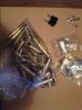
I have six of these connectors - enough for three blasters unless I'm mistaken. I don't want to make any profit or anything off these, I want you people to have them! Although I wouldn't say no to a trade ") PM me!
PM me!
here are five plus the one above. I saw someone post a pic of those big connectors above and I have a few nib but idk how they relate to this plug or anything lol
PM me!here are five plus the one above. I saw someone post a pic of those big connectors above and I have a few nib but idk how they relate to this plug or anything lol
Attachments
Country Paul
Sr Member
Has anyone else had any problems painting their Mitchell parts from shapeways?
I've used the same paints & process I've done on all my previous builds (including 3d printed parts) but for some reason the black paint won't dry & stays tacky
its not the paint because I've used it on other parts at the same time & it's dried fine
I used a light coat of grey primer, a light coat of silver (for weathering) & then a black top coat, it's the black that doesn't seem to want to dry
I've had 3 attempts now, each time taking the paint back off & lightly sanding back to bare plastic (worry I'm loosing detail now)
am I doing something wrong, is there some trick to painting these I've missed?
Did you wipe the 3D printed parts with acetone before painting/ washing them with soap and warm water (just like resin)?
Shapeways 3D printed parts have an oily/ waxy surface sometimes, internet forums state this stuff is used as a separator during the printing process.
What material did you choose for the print?
Markus
Shapeways 3D printed parts have an oily/ waxy surface sometimes, internet forums state this stuff is used as a separator during the printing process.
What material did you choose for the print?
Markus
Country Paul
Sr Member
It was my first time ordering from Shapeways, I just got the frosted detail plastic for both parts in the 10mm
I only saw the frosted detail or ultra detail options for the 2 parts I ordered
I prepped them like I do everything, washed & lightly sanded before priming but I didn't use acetone (is that like nail polish remover?)
They're in my garage drying at the moment so I'll see when I get home if it's happened again, this time I'd stripped the paint with white spirit & light sanding
I've actually ordered a pair of the aluminium brush rods from Gav now as I'd rather have metal anyway, I've also ordered another pair of the 10mm trans rotors from shapeways in the ultra detail this time hopefully they'll fit the Alu rods I'm getting & work out better (fingers crossed) will go to town on the cleaning
is it necessary to use primer/undercoat on 3d printed parts? I'd still like to persevere with these ones to possibly use on a Jawa blaster at some point & I don't like to be beaten by a prop
Im guessing that replica metal or inexpensive current close enough parts don't exist for these
Mara Jade's Father
Master Member
I need a set of those angled turntable parts. Does anyone know if there Is there a revision currently in work or if the currency version is the best we are going to get?
I've also ordered another pair of the 10mm trans rotors from shapeways in the ultra detail this time hopefully they'll fit the Alu rods I'm getting & work out better (fingers crossed) will go to town on the cleaning
is it necessary to use primer/undercoat on 3d printed parts? I'd still like to persevere with these ones to possibly use on a Jawa blaster at some point & I don't like to be beaten by a prop.Im guessing that replica metal or inexpensive current close enough parts don't exist for these
Toolguy didn´t modify the 3D models, based on the recent discoveries, until now afaik.
The real connector has a bore of 0,3752" (about 9,5mm). That´s why Toolguy offers two versions...one with a 10mm bore to work with his idealised stylus rods, one with the accurate 0,375" bore. BOTH should still work with Gavs replica brush rod, but you´ll have 0,5mm more room when inserting these into your 3D prints.
I didn´t prime my connectors.
Had them printed in ultra detail plastic, gave them a wash/ wip with acetone and put on some rub´n´buff befor painting black (2K automotive laquer)
Markus
- - - Updated - - -
I need a set of those angled turntable parts. Does anyone know if there Is there a revision currently in work or if the currency version is the best we are going to get?
like I wrote...toolguy didn´t not modify his drawings as of yet, but I am sure he can be convinced to do so easily
He just needs info about the correct length
Markus
Country Paul
Sr Member
Thanks Markus, I should probably asked the question before I ordered the 10mm ultra detail connectors :facepalm
Got an email from shapeways just now to say they shipped
But still 0.5mm doesn't sound like a lot & I assume only the internal diameter is different between the 2 connectors
Got an email from shapeways just now to say they shipped
But still 0.5mm doesn't sound like a lot & I assume only the internal diameter is different between the 2 connectors
toolguy301
Active Member
I would have addressed this some time ago but I have been out of commission for over a month with a broken ankle & surgery & have been stuck with my leg immobilized in the air. So haven't been able to work on anything so now I am trying to catch up on things.
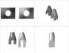
I spent some time today studying photos & updated the model for the trans rotor piece by lengthening it to 25 mm long. This is 5 mm longer than what is currently available. I am basing this off of scaling the reference photos & I am on the fence as to whether it should be at 25 mm or at 23.5 mm depending on the angle of measurement. The difference is only 1.5 mm (.060"). There aren't any good photos that I have been able to find.
Here is a photo rendering of the current & the revised trans rotor piece showing the 5 mm difference in length. Any input on this would be appreciated.
Attachments
Mara Jade's Father
Master Member
I would have addressed this some time ago but I have been out of commission for over a month with a broken ankle & surgery & have been stuck with my leg immobilized in the air. So haven't been able to work on anything so now I am trying to catch up on things.
You know how many times I've used that excuse?
Glad to see you're improving.
The part looks good to me but then again, I know nothing.
I was winding if you could help with a barrel to replace the bull barrel on the airsoft. I tried, you can see what I came up with here and the problems I have based on lack of skill and limited software: http://www.therpf.com/showthread.php?t=201887&page=5&p=3400004&viewfull=1#post3400004
toolguy301
Active Member
I was winding if you could help with a barrel to replace the bull barrel on the airsoft. I tried, you can see what I came up with here and the problems I have based on lack of skill and limited software
I had started looking into what it would take to make a new barrel, but didn't get too far. I have been planning on working on this. I am actually thinking I am just going to have to build one of these for myself just to have at this point & start procuring what I need to do this. This would be my second blaster build which will be way easier than my first one I did, which was my ROTJ EE-3. (http://www.thedentedhelmet.com/f20/scratch-built-rotj-ee-3-a-47899/) completely scratch built. I will see what I can come up with for the barrel.
Country Paul
Sr Member
I never have anything helpful or insightful to add to these discussion/research threads but I was looking through one of my books & found a picture of Greedo that I've not seen before in the threads,
ok so it's just a iPhone picture of a picture in a book but given how few pictures we have of this blaster I thought it was worth adding I'm sure everyone's seen it before & it's old old news but hey ho :lol
It's probably just the picture quality but the front of the Tomtit cylinder looks odd, like its smooth/solid
---------------------
thought I'd just add the other Greedo pics I'd gathered for reference, (these are just saved from image searches but if any of them aren't ok I'll delete them)
Attachments
-
 image.jpg1.1 MB · Views: 547
 -
 image.jpg193 KB · Views: 254
 -
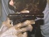 image.jpg1.1 MB · Views: 303
 -
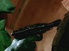 image.jpg76.8 KB · Views: 255
 -
 image.jpg201.2 KB · Views: 208
 -
 image.jpg12.4 KB · Views: 238
 -
 image.jpg93.3 KB · Views: 440
 -
 image.jpg56.7 KB · Views: 216
 -
 image.jpg70.1 KB · Views: 213
 -
 image.jpg17.5 KB · Views: 1,302
 -
 image.jpg25.4 KB · Views: 227
 -
 image.jpg49 KB · Views: 200
 -
 image.jpg213.6 KB · Views: 229
Last edited:
Dude, nice! Never seen these.
Is that rear push rod metal?! Why on earth would that be?
And I'm seeing something different in the cylinder cover over the ejection port. Don't see the reducers. Almost looks like a short piece of t track or something, with something longer extending towards the barrel? Maybe just a reflection.
Thanks for these photos!
Last edited:
Mara Jade's Father
Master Member
Any suggestions for fitting a real Mk1 rear sight to the airsoft body. The real sight is wider and will not fit into the slot.
Do I:
Do I:
- Try to widen the slot?
- Try to shorten the site?
- Create a 3D print of a site that will fit?
- Other?
Also, in those pics, proof that at least one version had a fat (resin cast) trigger guard. I completely forgot that you can freeze frame the movie and see that plain as day.
Also, still not seeing the sweep arm piece in the barrel. Still looks like a metal rod that was added to the casting for durability, then chopped off at the end. Not seeing a center hole, and the edge looks jagged, like a hacksaw was taken to it.
Also, still not seeing the sweep arm piece in the barrel. Still looks like a metal rod that was added to the casting for durability, then chopped off at the end. Not seeing a center hole, and the edge looks jagged, like a hacksaw was taken to it.
Last edited:
Similar threads
- Replies
- 2
- Views
- 476
- Replies
- 0
- Views
- 191
- Replies
- 3
- Views
- 345
- Replies
- 38
- Views
- 2,164