VectorZero,
I'm happy to share what information I can and I enjoy learning from the forum as well...there is an incredible depth of knowledge and experience here.
The software tools I mostly use are not proprietary. My workflow for a typical project is to leverage SynthEyes and/or PFMatchit for the 3D
view-correlation and tracking. I also use Modo or ZBrush for the 3D (modeling, texturing, rendering) and After Effects or Nuke for any compositing. Photoshop is ubiquitous throughout the entire process - especially the measuring tools (linear and angular measurements).
As for photogrammetry, that is an area of continued research and testing and thank you for the link, I hadn't seen that before. I've used 123D Catch for testing and proof of concept and Agisoft's Photoscan for the same, as well as professionally.
As for whether one moves the camera around a fixed object (and fixed lighting) or spin the object in front of a static camera and fixed lighting - I've had good success with both techniques using both tools. I would say from experience that the more "overcast" and flat your lighting is, you could use either approach. If, however, your lighting is contrasty and directional with a mix of deep shadows and directly lit areas, I would move the camera around the fixed object. The software tools love detail and texture - the more the merrier.
One advantage of spinning the object relative to a fixed camera is that your lighting gets averaged across the overall form. In other words, the resultant texture maps, attached to the derived geometry, exhibit very little modeling via lighting - just flat diffuse color.
For example:
[video=vimeo;80159816]http://vimeo.com/80159816[/video]
I shot the Panther Ausf. A rear deck donor kit part on a turntable in fairly flat overhead fluorescent shop lighting. I did move the camera but only along a vertical arc rotating from horizontal to vertical looking down and only to impart a greater degree of parallax and coverage of the overall part. I used my iPhone 4s and 123d Catch as an experiment.
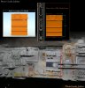
If I wanted to reverse engineer the part - I would use a high resolution laser scan like I did for the Entex Wankel parts in the 3D render frame I posted earlier in this thread (MF_donorPartSamples_001.jpg - although, the laser scan above is not complete as I only wanted major features on the part in 3D space to help me line up my 3D cameras).
Also, here is another photogrammetry test build using Photoscan:
[video=vimeo;80161404]http://vimeo.com/80161404[/video]
The stills that were used were primarily taken from underneath and facing aft. As you can see, the geometry and textures start to shear and stretch pretty quickly. The more pictures and angles fed into the software, gaps start to get filled in and the overall forms takes a more accurate shape.
Regards,
Andre
I'm happy to share what information I can and I enjoy learning from the forum as well...there is an incredible depth of knowledge and experience here.
The software tools I mostly use are not proprietary. My workflow for a typical project is to leverage SynthEyes and/or PFMatchit for the 3D
view-correlation and tracking. I also use Modo or ZBrush for the 3D (modeling, texturing, rendering) and After Effects or Nuke for any compositing. Photoshop is ubiquitous throughout the entire process - especially the measuring tools (linear and angular measurements).
As for photogrammetry, that is an area of continued research and testing and thank you for the link, I hadn't seen that before. I've used 123D Catch for testing and proof of concept and Agisoft's Photoscan for the same, as well as professionally.
As for whether one moves the camera around a fixed object (and fixed lighting) or spin the object in front of a static camera and fixed lighting - I've had good success with both techniques using both tools. I would say from experience that the more "overcast" and flat your lighting is, you could use either approach. If, however, your lighting is contrasty and directional with a mix of deep shadows and directly lit areas, I would move the camera around the fixed object. The software tools love detail and texture - the more the merrier.
One advantage of spinning the object relative to a fixed camera is that your lighting gets averaged across the overall form. In other words, the resultant texture maps, attached to the derived geometry, exhibit very little modeling via lighting - just flat diffuse color.
For example:
[video=vimeo;80159816]http://vimeo.com/80159816[/video]
I shot the Panther Ausf. A rear deck donor kit part on a turntable in fairly flat overhead fluorescent shop lighting. I did move the camera but only along a vertical arc rotating from horizontal to vertical looking down and only to impart a greater degree of parallax and coverage of the overall part. I used my iPhone 4s and 123d Catch as an experiment.
If I wanted to reverse engineer the part - I would use a high resolution laser scan like I did for the Entex Wankel parts in the 3D render frame I posted earlier in this thread (MF_donorPartSamples_001.jpg - although, the laser scan above is not complete as I only wanted major features on the part in 3D space to help me line up my 3D cameras).
Also, here is another photogrammetry test build using Photoscan:
[video=vimeo;80161404]http://vimeo.com/80161404[/video]
The stills that were used were primarily taken from underneath and facing aft. As you can see, the geometry and textures start to shear and stretch pretty quickly. The more pictures and angles fed into the software, gaps start to get filled in and the overall forms takes a more accurate shape.
Regards,
Andre
Andre
This is fascinating read. It's great to see industry guys helping out the fans.
Are the software tools that you are using proprietary? (I'm guessing so due to your day job.) The open source photogrammetry tools that I have discovered so far (excellent article here) rely on you taking overlapping photos from multiple different angles of an object to which you already have access. These tools seem to rely on identifying the same points from different angles, and they then build up a representative 3d mesh. When using them they specifically state not to hold the camera still and revolve the subject.
When trying to determine dimensions using analysis of still frames you are often dealing with a situation where the camera is locked off, and the model moves. Your original analysis seems to have been done from still frames and/or stills - suggesting a different approach or maybe different and more powerful software.
Right now I'm trying to work out the proportions of a model which doesn't have much in the way of greeblies to create a base reference. However, there is an existing kit which seems reasonably accurate, so I'm using that as the reference. I'm trying to infer from the stills what details I need to change, and its proving much harder than I thought - and the shapes are very simple rectilinear forms (viz. the upper part of ED-209's legs.)
Any tips? Or is this software only in the price range a VFX house can afford?
")