You are using an out of date browser. It may not display this or other websites correctly.
You should upgrade or use an alternative browser.
You should upgrade or use an alternative browser.
ESB AT-ST Turkey Walker (Chicken to the talented)
- Thread starter Guy Cowen
- Start date
- Status
- Not open for further replies.
qcfoundry
Sr Member
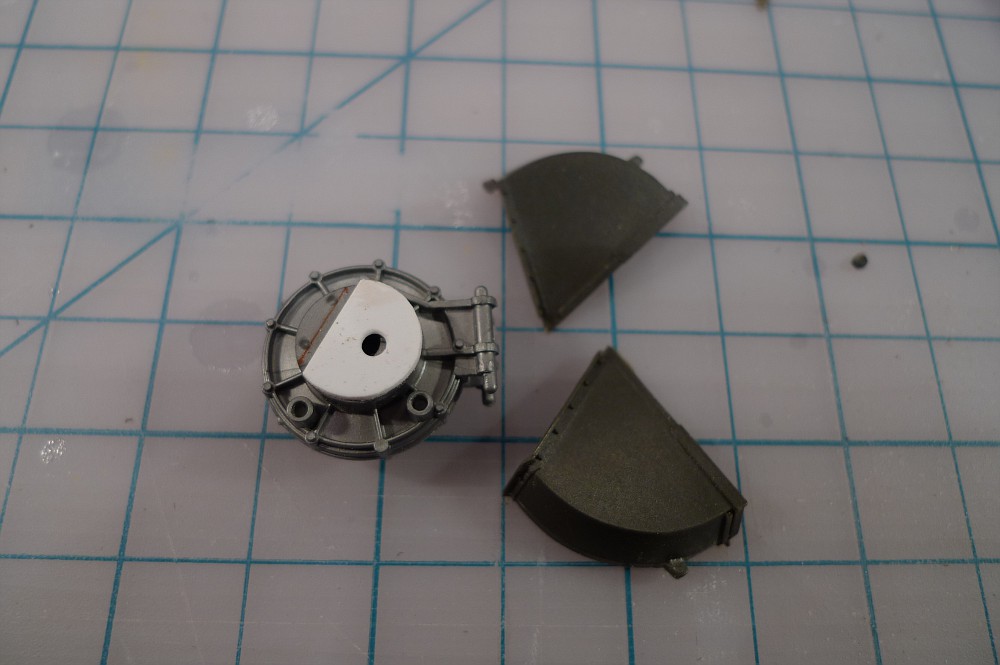
i added the shim between the transy and the fender

guy, you may breeze thru my photo album..
i tried to document all the little "tricks" that I learned along the way (that may not be evident after the build is finished). not saying i figured out everything -- i just tried to help others who may are trying this same path.
Thanks Q, Lee
I did add a shim to each of the tranny wheels but it isn't too thick to look off from the front. I noticed the the fender and tranny aren't flush on the prop but there is only a small gap though. I'm sure I can work it out though.
I've been studying all the threads like mad, such a shame Lee's Pics aren't around anymore.
Guy the gap on the prop is the fact the rivet detail on the DFV parts are still present.
I shaved mine off only where the fender joins, thus no gap buddy.
Think i still have my build pics, though Q has it pretty well documented for sure.
In any case, just ask before you cut mate, were all here to help you on!
Lee
I shaved mine off only where the fender joins, thus no gap buddy.
Think i still have my build pics, though Q has it pretty well documented for sure.
In any case, just ask before you cut mate, were all here to help you on!
Lee
Cheers Joe, its been a learning curve putting this thing together, I put the BT46 part on upside down yesterday and had to correct it and I was a bit gutted that the Vopser parts needed re working.
Have you had a chance to lay any parts down on the card armature or make a start on the chin guns?
Have you had a chance to lay any parts down on the card armature or make a start on the chin guns?
joewhite
Sr Member
We're lucky to have quite a few great AT-ST builders document their work. Learning curve aside, you are adding to that and really nailing the guns, IMO!
I had to go out of town from last Thursday til Monday so I haven't gotten much done. I did tear the molds apart to fix the curvature for the vac head plug and re-poured two heads. I'll let them dry for about a week before chopping them up and getting them ready for the second mold and cast. Fortunately, though, I got the shape all worked out.


I haven't worked on the leg/donor part comparisons yet. I started with the head as you can see. Not much to tell except that some of the donor part drawings are a tiny bit over-sized. I mean no disrespect there...I'm just pointing it out. But compared to reference pics, the placement looks close to perfect.
I'll start sticking donor parts on the cardboard legs Saturday morning.


Unfortunately, Guy, I'm in a bit of a rough spot with actually starting construction of the donor parts. I'll be starting a new job next spring and move to a new town in the summer. It seems like far away but I'd hate to actually start construction, move and risk breaking or losing parts. The move three years ago saw the demise of my AMT speederbike, breaks to my Horizon ED-209, and destruction of my Bluemoon B-Wing!
Therefore, until I move and set up a better shop, I've committed only to constructing the rough shapes for all the SS models I want to build. And also to acquire all the parts and supplies necessary.
Joe
I had to go out of town from last Thursday til Monday so I haven't gotten much done. I did tear the molds apart to fix the curvature for the vac head plug and re-poured two heads. I'll let them dry for about a week before chopping them up and getting them ready for the second mold and cast. Fortunately, though, I got the shape all worked out.


I haven't worked on the leg/donor part comparisons yet. I started with the head as you can see. Not much to tell except that some of the donor part drawings are a tiny bit over-sized. I mean no disrespect there...I'm just pointing it out. But compared to reference pics, the placement looks close to perfect.
I'll start sticking donor parts on the cardboard legs Saturday morning.


Unfortunately, Guy, I'm in a bit of a rough spot with actually starting construction of the donor parts. I'll be starting a new job next spring and move to a new town in the summer. It seems like far away but I'd hate to actually start construction, move and risk breaking or losing parts. The move three years ago saw the demise of my AMT speederbike, breaks to my Horizon ED-209, and destruction of my Bluemoon B-Wing!
Therefore, until I move and set up a better shop, I've committed only to constructing the rough shapes for all the SS models I want to build. And also to acquire all the parts and supplies necessary.
Joe
qcfoundry
Sr Member
as i response to those who have been using my templates to cut the head, and finding discrepancies--
i'm currently on a different project and discovering an ugly truth. my CAD isn't printing perfectly. when i print at a 1:1 scale, i'm loosing a 1/16" over 12". i'm assuming that may have happened when i cut the templates and sent them with my pulls. this may ALSO be happening for others printing off my CAD file. i recommend everyone test measure a/the scale once its printed off.
trully apologize for this faux pas.
learning -- always double check all steps along a process, and never assume.
if any other CAD savvy individuals know the fix for this, i'm all ears. (i've printed on 3 different machines and getting the same result -- think its the file/setting, not the hardware). thanks
MonsieurTox
Master Member
Q, I have the same problem printing my .AI files... Not a big deal with small parts, but when it comes to large parts...
qcfoundry
Sr Member
Q, I have the same problem printing my .AI files... Not a big deal with small parts, but when it comes to large parts...
Thats crazy interesting. I was assuming it was an setting in AutoCad, but may be a vector file thing? Yeah, it really accumulates over long distances -- i'm only needing about 24" max....can imagine the problems with your SD. Did you come up with a solution to this? Was think'g of paying a professional print shop print it out, and let them figure it out, lol.
MonsieurTox
Master Member
No, unfortunatly I live with it with small parts, for the biggest, I print them and adjust (enlarge) the .ai files, maybe it could be from the vector files or, maybe that's the home printers are not precise enough, I really don't know... But sometimes it's really annoying.
qcfoundry
Sr Member
No, unfortunatly I live with it with small parts, for the biggest, I print them and adjust (enlarge) the .ai files, maybe it could be from the vector files or, maybe that's the home printers are not precise enough, I really don't know... But sometimes it's really annoying.
(promise, last time i go OT)
found out i was off (almost exactly) 1/16" per 12" length.
so i scaled up my drawing 192/191 (12*16=192)...and works perfectly..in the X & Y axis (wasn't a printer problem). Julien, perhaps if you scale yours up 100/99 (assuming your's is a metric drawing)?
MonsieurTox
Master Member
(last time OT too, sorry !)
Yeah my drawings are metric, I think you're right, it's something like about 101% ! Just enough to put your in trouble when assembling hundreds of parts on a 120 cm long frame ! :lol
Yeah my drawings are metric, I think you're right, it's something like about 101% ! Just enough to put your in trouble when assembling hundreds of parts on a 120 cm long frame ! :lol
joewhite
Sr Member
(same here...last OT call  )
)
Quincy,
Doh! I see what you mean. Therefore my added dimensions are also wrong since I imported the .pdf file (which I take you plotted from AutoCAD) into the program I use. The program I use, Laser Master 8, faithfully reproduced the drawings. Unfortunately, it also inherited the discrepancy.
It looks like I will also have to redo the head vac-plug molds. The side panels are ok since the loss occurs at the unused, excess ends. But since the loss happens horizontally, the top and front plate are just a tad too thin.
It's a setback, but oh well. I, personally wouldn't have made it this far without the work of Q, Lee, Allan and Jason. I'll have to play with the scale of the blueprints in Laser Master 8.
Round two......let's get it on! :cool
Joe
joewhite
Sr Member
Guy,
Yup. I use Laser Master 8. I'm no engineer but it's a pretty powerful vector tool, IMO. I used the dimension tool which snapped to the desired points. I really didn't have control over the measurements....only in picking the points which I was really meticulous about. So, had the .pdf been correct, the dimensions would also.
An example of accuracy...below is a pic of the program in work taking the measurement of the thin view of Part #8, the upper leg. The black arrow shows the chosen vector object highlighted in red and showing the square points. The green arrow points to the actual measurements of the chosen object which is automatically detected by the program. And finally the blue arrow shows the result of the dimension tool. It's the same measurement that the program detected only laid out in the dimension format of your choice....much like AutoCAD.

I'm not trying to sound smug or anything. I simply want to show how I acquired the dimensions in case anybody wanted to know.
The original .pdf Quincy sent me, which was then imported into LM8, shows Part #8 to measure the same as above. So the discrepancy was faithfully reproduced in LM8.
My thing is that I am, for the most part, not AutoCAD savvy. I failed to confirm whether the .dwg matched the .pdf and my .ve file. As Q mentioned, the loss happens when you plot and/or export from AutoCAD. I'm wondering if plotting to a CNC machine would yield the same discrepancy.
Joe
Yup. I use Laser Master 8. I'm no engineer but it's a pretty powerful vector tool, IMO. I used the dimension tool which snapped to the desired points. I really didn't have control over the measurements....only in picking the points which I was really meticulous about. So, had the .pdf been correct, the dimensions would also.
An example of accuracy...below is a pic of the program in work taking the measurement of the thin view of Part #8, the upper leg. The black arrow shows the chosen vector object highlighted in red and showing the square points. The green arrow points to the actual measurements of the chosen object which is automatically detected by the program. And finally the blue arrow shows the result of the dimension tool. It's the same measurement that the program detected only laid out in the dimension format of your choice....much like AutoCAD.

I'm not trying to sound smug or anything. I simply want to show how I acquired the dimensions in case anybody wanted to know.
The original .pdf Quincy sent me, which was then imported into LM8, shows Part #8 to measure the same as above. So the discrepancy was faithfully reproduced in LM8.
My thing is that I am, for the most part, not AutoCAD savvy. I failed to confirm whether the .dwg matched the .pdf and my .ve file. As Q mentioned, the loss happens when you plot and/or export from AutoCAD. I'm wondering if plotting to a CNC machine would yield the same discrepancy.
Joe
imaginager
Sr Member
Quincy and I exchanged the DWG file countless times over the course of our remote, collaborative development of the v2 armature, which used my v1 as the starting point...which used Isel's master pattern as the initial basis of comparison. BTW, since then I developed additional revisions (replacing the main chassis, and a few other parts), which I had machined as a one-off via a very talented machinist in New Zealand. This just goes to show that this work will always be evolving and new blood in the scratch-building arena will really help to drive accuracy.
Anyway, during v2 development, I used MicroStation, which will read AutoCAD natively. I think the problem is with the printing, not with AutoCAD export. Unless you mean the export to PDF, which is likely impacted by Windows. I don't know about AutoCAD, but in MicroStation you're at the mercy of Windows printer drivers. It's important to make sure that 1" = 25.4mm and all the obnoxious "scaling" settings are set correctly to get a true scale print to PDF Creator.
Anyway, during v2 development, I used MicroStation, which will read AutoCAD natively. I think the problem is with the printing, not with AutoCAD export. Unless you mean the export to PDF, which is likely impacted by Windows. I don't know about AutoCAD, but in MicroStation you're at the mercy of Windows printer drivers. It's important to make sure that 1" = 25.4mm and all the obnoxious "scaling" settings are set correctly to get a true scale print to PDF Creator.
- Status
- Not open for further replies.
Similar threads
- Replies
- 15
- Views
- 1,400
- Replies
- 9
- Views
- 1,019
- Replies
- 26
- Views
- 5,073


