tekparasite
Member
Here's what I have found so far. My hope is that people using this method will be able to make their equipment work depending on the chipset in their electronic board.
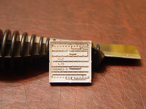
NOTE: It looks like SureElectronics has switched to a new chipset from HT1632 (old) to HT1632C (new)
Q: How do you which chipset is in your electronics board?
A: One way is to test the different code sets to see which one works.
The code that works with the old chip is here. The code that works with the new chip is here. If you buy the board from their website, chances are you'll get the new chip set. Some old boards are still floating around on Ebay
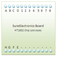
Q: What's the mapping to the old board?
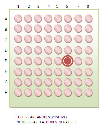
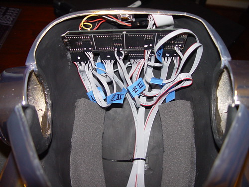
A: Given the matrix labels referenced below, here are the pin mappings for the OLD board with 5mm LEDs.
Q: What's the mapping to the new board?
A: Given the matrix label referenced below, here are the pin mappings for the NEW board with 3mm LEDs.
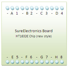
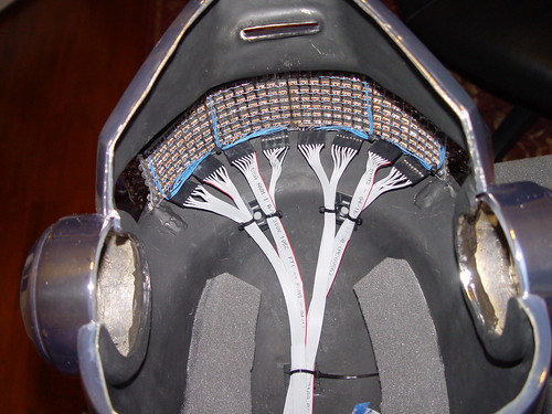
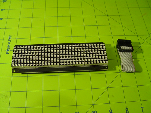
Matrix Label Reference
The wiring between Arduino and the SureElectronics board remains the same.
I hope that helps.
NOTE: It looks like SureElectronics has switched to a new chipset from HT1632 (old) to HT1632C (new)
Q: How do you which chipset is in your electronics board?
A: One way is to test the different code sets to see which one works.
The code that works with the old chip is here. The code that works with the new chip is here. If you buy the board from their website, chances are you'll get the new chip set. Some old boards are still floating around on Ebay
Q: What's the mapping to the old board?
A: Given the matrix labels referenced below, here are the pin mappings for the OLD board with 5mm LEDs.
Q: What's the mapping to the new board?
A: Given the matrix label referenced below, here are the pin mappings for the NEW board with 3mm LEDs.
Matrix Label Reference
The wiring between Arduino and the SureElectronics board remains the same.
I hope that helps.
Last edited:


") . So each had to have one.
. So each had to have one.