Studio Scale TOS Enterprise(11.25 feet)

Here is another update.

All of the big parts for the E have been machined.
Now for the fun of fitting and finishing the parts.

My router plays a role in this.
dscn2043vl.jpg

The parts are a profile and a cradle for the secondary hull.
I did the same thing for the engine.

dscn2050.jpg

here is one half of the hull in the cradle. This makes things easier to handle, and helps to protect the parts. Each of the parts that cradle the hull are a 1/8" larger than the parts they hold. This allows some room for padding after the hull has been finished.

The cradle that's more impressive is the nacelle cradle.
dscn2057u.jpg

It plays a very important roll, since the nacelle is in 4 parts. The parts have to be aligned for mating. Note the steel plate the cradle is sitting on. It's 3" thick 2' wide and 3' long(it's about 600 pounds:)). It was from a machine I designed that didn't work, but some of it's components come in very handy. This plate is precision ground, that means the surface is really flat. Not perfect mind you, but more than enough for model work. The slots in the plate are called T-slots so I can bolt things to the plate. The plate and the cradle work together to help make things straight.
dscn2047u.jpg

I don't care that the cradle is hanging off each side(besides I couldn't help it). As far as alignment goes it's fine. Note the line of MDF between the nacelle half's. That is what I use to match and eventually mate the parts.
This is what it looks like.
dscn2052f.jpg

It has a series of holes for pins, each piece of the nacelle has these holes. I use them to align parts in the router, as well as for this purpose. It saves a lot of time, and headaches especially when things go wrong.
dscn2055f.jpg

The 2 slots in the middle of the template are there so I can route(using a hand router) channels for steel bar to mate the halves(I haven't done that yet).

dscn2058w.jpg

Here is a close up. The parts are just set in the cradle, the alignment is very good.
Here is one part of the trick to getting a good alignment.
dscn2060y.jpg

There are tabs at each end of the cradle. These allow me to place the parts right where I want them, then the template will do the rest.

I did start working on mating the neck to the second hull.
dscn2045r.jpg

I figured you guys wold like this view. It's hard to use a camera with one hand, and try to get a good shot.

That's it for this update, I would have had more done if things were not so cold. Phoenix has been down in the 40's which makes my garage feel like a meat-locker. For Phoenix that's really cold, but then to my thin blood anything below 70 degrees is cold. Before I hear people say that's not cold, keep in mind our summers can get above 120 degrees. It's all relative.
 
This is awesome!!! Really looking forward to following your progress and I appreciate your detailed updates.
 
Last edited:
Do you plan an interior support structure for the eventual (I assume) epoxy glass model?

I question if it's necessary for my smaller 66 inch version if I build the secondary hull and pylons from thick layup Matt and a light layup for the saucer and nacelles with glass cloth.

I suppose in terms of engineering and structural strength size does matter. Meaning a small 1/350 model needs no such support but as the size increases and the mass - weight it does.

Certainly at the original 11.5 foot it will?

Steve
 
Last edited:
ATM,
I very much like the idea of the cradle you have for the secondary hull.

You should give serious consideration to making it the stand for whatever kit you come up with as a result of your efforts. perhaps made out of clear lucite or other such material, but I think it would be much more preferable to the "ship on a stick" pole type stand
 
As a friend pointed out, I plan everything. Something which this hobby isn't known for. I consider this a design project which means I have completed the design before I get to the machining stage. The armature to me is the most important part of the design. You can do almost anything with cosmetics, but a bad structure makes the whole thing a failure. If the model starts to sag in a few years, then it's a waste of time.

Do you plan an interior support structure for the eventual (I assume) epoxy glass model?

I question if it's necessary for my smaller 66 inch version if I build the secondary hull and pylons from thick layup Matt and a light layup for the saucer and nacelles with glass cloth.

I suppose in terms of engineering and structural strength size does matter. Meaning a small 1/350 model needs no such support but as the size increases and the mass - weight it does.

Certainly at the original 11.5 foot it will?

Steve
The model is going to be a fiberglass shell with an aluminum armature. On your 66" your going to need an armature, the 66" I have has a 1/4" acrylic armature in the secondary hull and saucer(A 66" model is a good sized model, even using acrylic may not be enough). The pylons are resin with an aluminum tube cast into place. But they rely on the fiberglass of the secondary hull for support. That's a real weak spot, because the glassing work on the model is suspect. I have parts changing shape on their own, so even after I complete that model I will be looking for problems.

The structural problems with the TOS E design are complex but not that complex. There are two critical areas on the model.
emoments.jpg

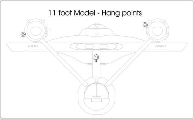
The white arrows on each end of the model signify gravity. See how far they are from the secondary hull. These cause stress on all of the points I have circled. The primary hull isn't that hard because it has a lot of room for structure. But the engines pose bigger issues.
emoments2.jpg

The spindly pylons(I think they are a joke) are a problem because they would twist about their base. If you used a weak material without any additional support. Or put to much weight into the nacelles. You'll eventually have a really warped ship.
You'll have to do it Steve, or you could do what the other guy did that made a 66" E, hang it from the ceiling on strings. He's not going to be very happy with his ships down the road(if he isn't already).

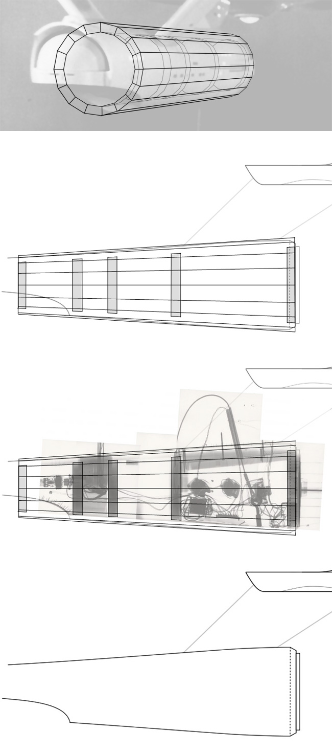
My pylons are going to be a fiberglass shell, with a 1"x3" aluminum tube for support. Those are going to bolt into the 1/4" aluminum armature in the secondary hull. This is where things get interesting.

pylonstructure.jpg

This shows what I'm doing in section. The pylon support slides into slots milled into aluminum plate. If you'll notice the rectangular slot in the secondary hull plate. It(there are 4) will slide into corresponding slots in the armature of the 2nd hull. That's so I don't have to weld anything, they will just set in place with gravity's help.

All this why there is box shapes on each side of my pylon patterns.
dscn2017m.jpg

So the parts will be the correct length, and correctly positioned within the pylons. This structure prohibits a shuttle bay in the model. Since I don't know how far back it goes into the hull, I'll bet it would interfere with the model's structure. As well being able to break down the model should it need to be moved.

I would follow similar rules even with the 350 version of the ship. But that doesn't mean using metals, but since metals are relatively cheap for such a small model it would be a lot easier to epoxy into place.

ATM,
I very much like the idea of the cradle you have for the secondary hull.

You should give serious consideration to making it the stand for whatever kit you come up with as a result of your efforts. perhaps made out of clear lucite or other such material, but I think it would be much more preferable to the "ship on a stick" pole type stand
I'm doing just that, it will be a ship on a stick. But 1" the stick is a 1" steel tube with a 1/2" center(for electrical). Keep in mind the amount of force required to make the steel bend is so extreme, you could pick up a full size pick-up truck, and the bar will only deflect slightly. That will be going into an aluminum armature.

A cradle is not practical for display purposes and it would pose additional problems(the cradles I made are for matching and finishing purposes), plus it wouldn't change anything in the structure of the model. And it would have to still have to be anchored to the model. The shell of the model will be supporting very little. It would really detract from the look of the model, as well as having a very awkward base. I have that designed as well, it will be a piece of furniture(on casters). So I can display more things below the model. And keep the model high enough to be able to walk under the primary hull.

Here is a rough sketch of the armature in the 2nd hull.
2nhullnotfinal.jpg

This is very rough, I'm still working on the details. There are a lot of them. Such as the 1" slot in the bottom, that will be a tube for the model to set on(with set screws), the wiring will run out of the tube into the hull. It would be impractical to have a connection like the MR E. Since this isn't a model you can fly around the room.
It does show what I'm thinking, and there is another point of trouble. That is the connection to the primary hull. Other models(the MR E & jk 66") you cannot remove the primary hull from the second(not without a lot of work). On this model if I couldn't remove the the primary hull, it would be very impracticable to move(or ship for that matter). I have the solution but that will have be to another post.

Questions? Comments?
 
Fascinating stuff, ATM. Thanks again for sharing in the process! This labor of love will be worth a lot when she's finished. I don't know how you could ever put a price tag on your sweat and toil but I'm curious: are you planning on coveting her or after recording her attributes for posterity--and smashing the proverbial champagne bottle across her bow--will you put it up to market to the highest bidder?
 
Fascinating stuff, ATM. Thanks again for sharing in the process! This labor of love will be worth a lot when she's finished. I don't know how you could ever put a price tag on your sweat and toil but I'm curious: are you planning on coveting her or after recording her attributes for posterity--and smashing the proverbial champagne bottle across her bow--will you put it up to market to the highest bidder?
The first two are for me.

It's a ship I've always wanted, and the two I'm keeping are my payment for all the work I could never get paid back for.

After that, I'm considering the market.
 
Thanks you so much! I found that extremely helpful and eye opening. Working with Aluminum is nice. Easy to cut and light weight. Bolts together without cracking. I like it.

Same here. I'm making one for me because it's something I've always wanted since I was in High School. The second one I'll sell. I may offer some hull kits and the builder supply everything else(lights, internal structure, etc). Even at my smaller scale these models aren't cheap to make. The silicone epoxy molds alone will cost a 1500.00 or more and that doesn't include the labor.

Thanks again for the help and lecture. ;)

Steve
 
Awesome work, and mini-tutorial. I agree w/Steve, very cool!

Back in the stone age, I had such issues with my AMT Enterprise. My 10 year old self decided to take a lesson from braces on teeth- Glue the pylons & tape them solidly into the correct position, and... leave it for a few days before removing the tape. Jeeze, I used a whole roll on each one I did, but it worked!

We learn by doing, I guess.:lol
 
ATM,
You're right.

I was thinking of the secondary hull as a solid shape, not a fiberglass shell over an armature. Your method of weight displacement is much more elegant.

which got me thinking. what would happen do you suppose if after you completed your secondary hull (lighting wiring and such) you filled the whole shape with epoxy. You'd be sealing the LEDs in place permanently (along with everything else) but think of the stability youd be gaining
 
ATM,
which got me thinking. what would happen do you suppose if after you completed your secondary hull (lighting wiring and such) you filled the whole shape with epoxy. You'd be sealing the LEDs in place permanently (along with everything else) but think of the stability youd be gaining

Wow, what would that weigh though?
 
What got me thinkig about filling the hull is looking back on the Original 11 footer and how much of her is solid and I can't help thinking that has a lot to do with how little droop she is showing even after 40 years.

Solid body + solid pylons + mostly hollow nacelles = more stability in maintaining the shape


Yeah, that certainly makes sense. Still, you can have a solid stone hull but if the pylons-hull, pylons-nacelles and "neck"-saucer connections are not super-rigid, you WILL have problems. But the studio model had ample room in the engineering hull for the electrical wires of which there were plenty added. Of course, AMT model won't have lighting on just the starboard side, with a large area of the port side of the hull dedicated to wire access as the studio model had. On the other hand LEDs are much more space-economical.

I think a more important factor in preventing nacelle and saucer droop would be to reinforce the weak spots as AMT outlined by utilizing very rigid armatures and as light as possible materials for the nacelle and saucer shells. Master Replicas tried the metal armature but the vast majority from what I've gathered--if not all--of those models were not spared the droops to one degree or another. Not sure why really... maybe it had to do with the "Made in China" execution.
 
Last edited:
Here is the Original E-
originalep.jpg

The stand it sits on tells me there might be some issues. But it has stood up well. Considering it wasn't built to last(just through the series photography), nobody expected it to still be around after 47 years.

2ndpilotside.png

That solid hull is why the windows below and forward of the pylons were not lit.

Making things solid is not always a good thing. Even solid objects can deform over time(I've seen stone columns bowing outward under a load) . It's best to keep things light as possible, with a structure that has more strength than you would ever need. And in the case of this type of model you need to gain access to the interior. The last thing you want to have to do is rebuild a portion of the model just to change a burned out light.

I'm not worried about the stability of the structure, since I'm using aluminum it would be very stable. Now metals can flex, but since the model will be made of fiberglass. It would be nowhere near the weight that would make the metal flex. Plus fiberglass can be layered up to be very strong(even stronger when bonded to the aluminum) and it only has to support itself. All of this I considered when I was designing the model.

It's my hope that some of you take this info into consideration with your own builds. Whatever subject they are, I assume you guys are like me. When you build a model you want it to last.
 
While the supports and dorsal were solid, the secondary hull wasn't. It was built like a barrel, with open cavities inside. The reason for the lighting being the way it was was because they cut holes in the front and back to access the forward most and rear most cavities. All the wiring between was taped to the outside of the hull until the model was modified to serve as a display piece.

This is approximately what the unturned barrel structure look like...

sh_assembly-x.jpg


As for the strength and longevity of the original model, for a good portion of it's life it was hanging rather than sitting. In that hanging position, the weight of the model was supported via points on the nacelles and the dorsal (though most of the weight was carried by the dorsal point).

11ft_hang-points.jpg


Before the model was modified for the second pilot, the model was filmed hanging from a single wire that passed through a channel hole in the dorsal to an anchor point at the bottom the the front cavity of the secondary hull... a point that still exist today (and can be seen in the x-rays of the model).

Of course none of that has any baring on this model project.

But one thing you might consider... the way the original model's nacelles were built, half the weight of them was originally in the front third of the nacelle. They were almost balanced about the point where the supports attached to the nacelle. So having hollow nacelles might not be enough, you might want to add weight to the front end of them to help keep them true.
 
given this evidence, I would amend my original thought of solidifying the entire secondary hull to just the section between the two barrel stays on either side of the pylons
 
This thread is more than 8 years old.

Your message may be considered spam for the following reasons:

  1. This thread hasn't been active in some time. A new post in this thread might not contribute constructively to this discussion after so long.
If you wish to reply despite these issues, check the box below before replying.
Be aware that malicious compliance may result in more severe penalties.
Back
Top