You are using an out of date browser. It may not display this or other websites correctly.
You should upgrade or use an alternative browser.
You should upgrade or use an alternative browser.
Looper Blunderbuss - Pics of Painted Slushcast Kit on pg. 18
- Thread starter FakeBritishAccent
- Start date
Re: Looper Blunderbuss - WIP pics begin on Page 3
This is such a fantastic build! The quality is just outstanding. I'm sooooo happy to add one of these to my sci-fi guns collection!
I'm totally just gonna stand around my house holding this thing, looking at clocks, and seeming impatient. :lol
This is such a fantastic build! The quality is just outstanding. I'm sooooo happy to add one of these to my sci-fi guns collection!
I'm totally just gonna stand around my house holding this thing, looking at clocks, and seeming impatient. :lol
Re: Looper Blunderbuss - WIP pics begin on Page 3
@Fakebritishaccent
http://i.imgur.com/IrT3T.jpg
Great Work so far, really impressed.
Do you think you could help me out with the measurements of your blunderbluss ? I attached a jpeg of what would be helpful and broke it down into segments so that you could just list the measurements in your response. Would be of great help in helping me make my blunderbluss. Also if you could measure the height or width of the barrel. I'm using a mailing tube as the shaft and want to know what size I should get.
ie.
a:2''
b:1'
c:8''
d:2''
Thanks in advance for your help!
( I'm attempting to make one using non metal materials so that I may take it into clubs and events. I don't think they would let me take in one with a solid metal frame like your yhm-5005.)
FakeBritishAccent
Sr Member
Re: Looper Blunderbuss - WIP pics begin on Page 3
No problem, dude!
a: 6"
b: 2"
c: 12"
d: 3 1/2"
Also, the diameter of my inner aluminum tube is about 1 3/4"...but since you're making yours from scratch, you can use whatever diameter tube you want! The only reason mine had to be exact is because I had to fit it into the YHM-5005.
So here's a quick (picture-free) update. I laid down more Apoxie Sculpt to build up the grip of the slide, then after it cured I knocked it down to roughly the proper thickness. After I got it fairly smooth and symmetrical, I used more Apoxie Sculpt to build up the "lip" that the grip on the slide has.
After hitting the rear endcap with a shot of flat black, I used 220 grit sandpaper and some Bondo Spot Putty to smooth out some dings and get rid of a lil' bit of wood grain on the sight. I'm going to use thin, flexible plastic to join the second and third rings of the rear endcap to the first ring, then I'll reinforce the gap with more Apoxie Sculpt on both the outside and the inside. After I'm done, it should fit onto the aluminum tubing snugly and securely...but I'll still drill a couple mounting holes through it just in case.
Since the all the components of the grip/gripframe are all completed, I'll be assembling, painting, and weathering the grips sometime tomorrow. After they're perfectly colored, I'll go to Sports Chalet to pick up some hockey tape in order to almost completely cover the paintwork on the grip :cry
So that's that for now. Thanks for reading!
-Jonaas
@Fakebritishaccent
http://i.imgur.com/IrT3T.jpg
Great Work so far, really impressed.
Do you think you could help me out with the measurements of your blunderbluss ? I attached a jpeg of what would be helpful and broke it down into segments so that you could just list the measurements in your response. Would be of great help in helping me make my blunderbluss. Also if you could measure the height or width of the barrel. I'm using a mailing tube as the shaft and want to know what size I should get.
ie.
a:2''
b:1'
c:8''
d:2''
Thanks in advance for your help!
( I'm attempting to make one using non metal materials so that I may take it into clubs and events. I don't think they would let me take in one with a solid metal frame like your yhm-5005.)
No problem, dude!
a: 6"
b: 2"
c: 12"
d: 3 1/2"
Also, the diameter of my inner aluminum tube is about 1 3/4"...but since you're making yours from scratch, you can use whatever diameter tube you want! The only reason mine had to be exact is because I had to fit it into the YHM-5005.
So here's a quick (picture-free) update. I laid down more Apoxie Sculpt to build up the grip of the slide, then after it cured I knocked it down to roughly the proper thickness. After I got it fairly smooth and symmetrical, I used more Apoxie Sculpt to build up the "lip" that the grip on the slide has.
After hitting the rear endcap with a shot of flat black, I used 220 grit sandpaper and some Bondo Spot Putty to smooth out some dings and get rid of a lil' bit of wood grain on the sight. I'm going to use thin, flexible plastic to join the second and third rings of the rear endcap to the first ring, then I'll reinforce the gap with more Apoxie Sculpt on both the outside and the inside. After I'm done, it should fit onto the aluminum tubing snugly and securely...but I'll still drill a couple mounting holes through it just in case.
Since the all the components of the grip/gripframe are all completed, I'll be assembling, painting, and weathering the grips sometime tomorrow. After they're perfectly colored, I'll go to Sports Chalet to pick up some hockey tape in order to almost completely cover the paintwork on the grip :cry
So that's that for now. Thanks for reading!
-Jonaas
FakeBritishAccent
Sr Member
Re: Looper Blunderbuss - WIP pics begin on Page 3
Quick pic update!
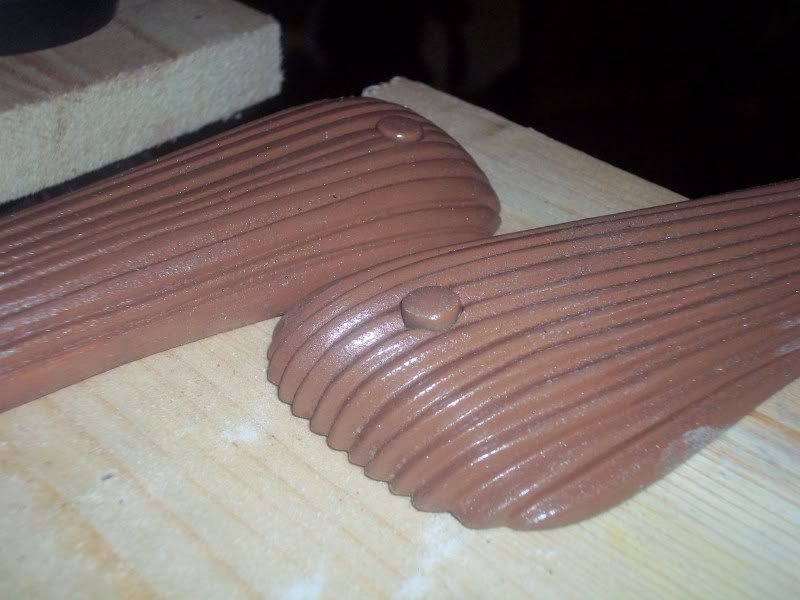
The finished grips ready for painting! I was able to knock back most of the sawdust I'd clearcoated onto the piece. Now the grips have a bit of gritty texture, but nothing overblown. The grip screw "plugs" are friction fit in place so the screws can be exposed and the grips removed for servicing. Of course, I'd have to tear through a bunch of hockey tape first...but it's nice to know I have the option.
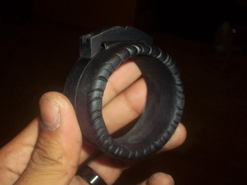
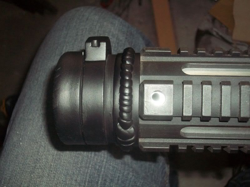
Just wanted to put up a shot of the rear endcap's second and third rings, all smooth and painted up. I'm INCREDIBLY happy with how this piece turned out.
There's still a few small details left on this piece, and if there's time, I MAY resculpt parts of the weld line...but for now, I'm calling it done.
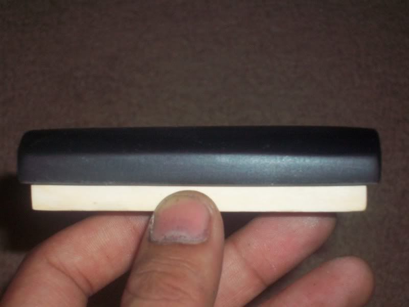
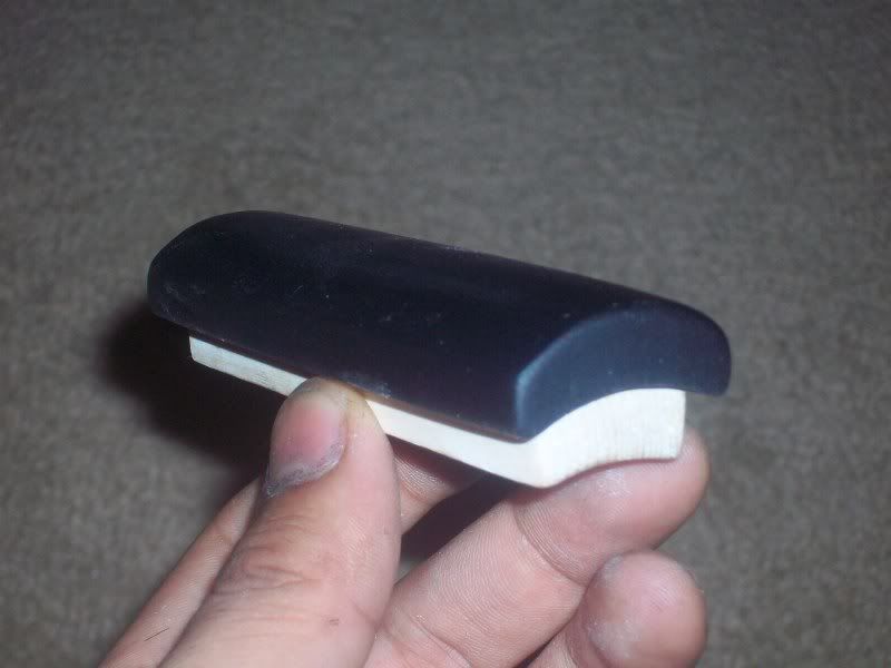
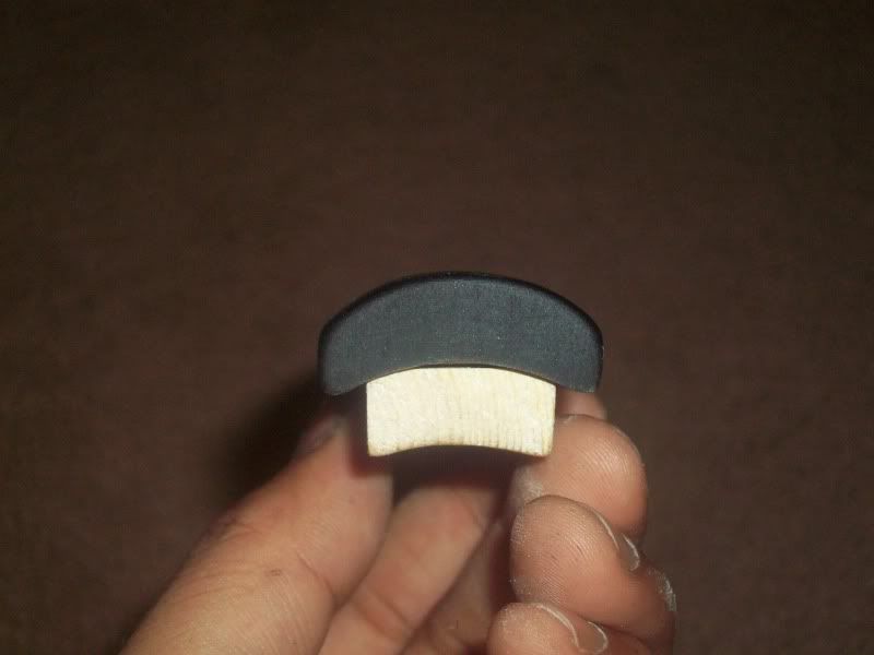
A series of pics detailing the sculpting of the slide's grip. It's been a fun challenge getting this sucker completely smooth and symmetrical, but now it's ready for final detailing. I'll be sculpting/carving those details in tonight and after the Apoxie Sculpt cures, I'll have to drill through it all in order to mount the grip to the slide base.
So that's it for now! Back to work!
-Jonaas
Quick pic update!
The finished grips ready for painting! I was able to knock back most of the sawdust I'd clearcoated onto the piece. Now the grips have a bit of gritty texture, but nothing overblown. The grip screw "plugs" are friction fit in place so the screws can be exposed and the grips removed for servicing. Of course, I'd have to tear through a bunch of hockey tape first...but it's nice to know I have the option.
Just wanted to put up a shot of the rear endcap's second and third rings, all smooth and painted up. I'm INCREDIBLY happy with how this piece turned out.
There's still a few small details left on this piece, and if there's time, I MAY resculpt parts of the weld line...but for now, I'm calling it done.
A series of pics detailing the sculpting of the slide's grip. It's been a fun challenge getting this sucker completely smooth and symmetrical, but now it's ready for final detailing. I'll be sculpting/carving those details in tonight and after the Apoxie Sculpt cures, I'll have to drill through it all in order to mount the grip to the slide base.
So that's it for now! Back to work!
-Jonaas
TheShinyOne
Well-Known Member
Re: Looper Blunderbuss - WIP pics begin on Page 3
Just saw the trailer last night, nice build choice!
Just saw the trailer last night, nice build choice!
Lunaman
Sr Member
Re: Looper Blunderbuss - WIP pics begin on Page 3
Trailer? Go watch the movie! :lolJust saw the trailer last night, nice build choice!
FakeBritishAccent
Sr Member
Re: Looper Blunderbuss - WIP pics begin on Page 3
Get to it, dude! I'm already on my THIRD viewing!
Trailer? Go watch the movie! :lol
Get to it, dude! I'm already on my THIRD viewing!
FakeBritishAccent
Sr Member
Re: Looper Blunderbuss - WIP pics begin on Page 3
After a couple podcasts worth of work, it's time for a HUGE pic update!
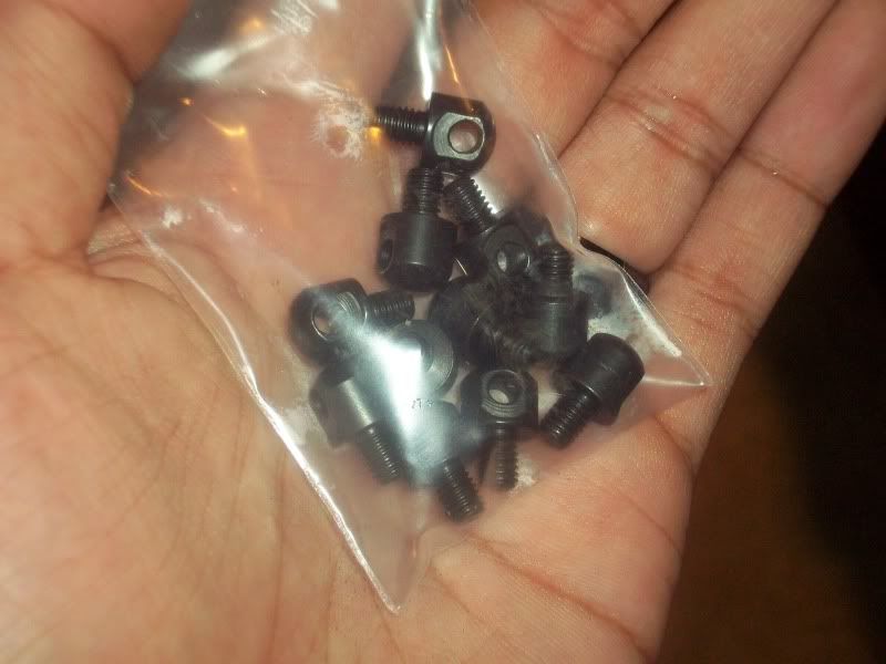
Who knows where THESE suckers go? Hint: They're the ONLY metal parts that I'm including in the resin blunderbusses. Find out at the end of this post!
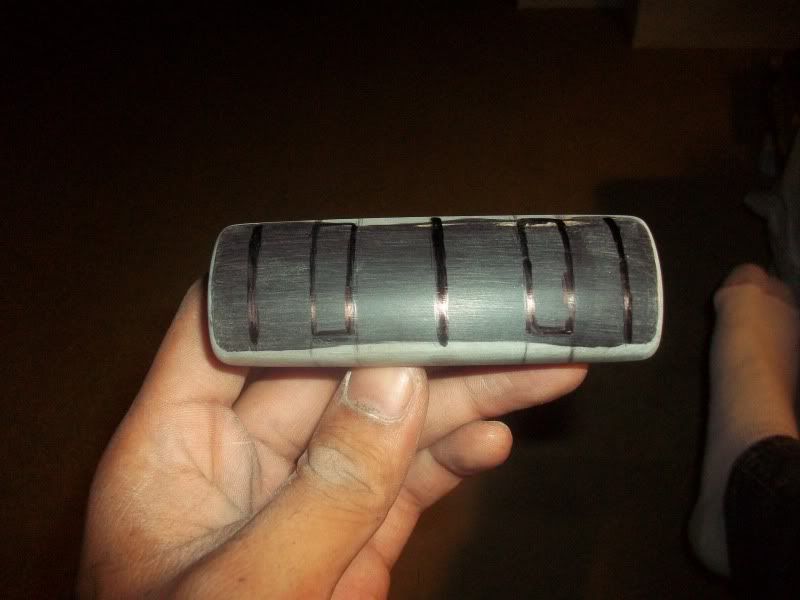
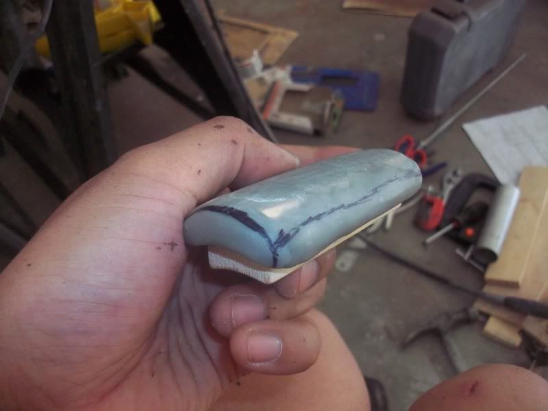
After getting the grip of the slide nice and smooth, I went about detailing it. First, I plotted out the relative placement of everything with a Sharpie.
The holes I'm using to mount the grip to the slide base were already pre-drilled.
I roughly sculpted on the "nubs" of the grip with Apoxie Sculpt and used my Dremel and a round file to cut in the notches.
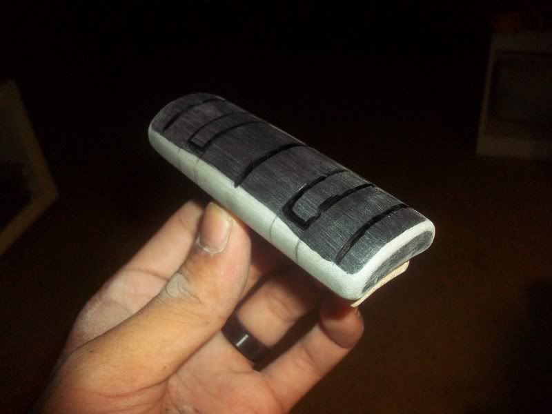
After the Apoxie Sculpt cured, 220 grit sandpaper was used to clean everything up and make it nice and smooth. Gaps were filled with Bondo Spot Putty.
Finally, a shot of flat black to see how it all squared away.
This piece has since been further altered, as the "nubs" have a more rounded edge to them. I still need to find the proper screws to mount the slide grip to the slide base, but other than that, this slide is 100% DONE.
A shot of the final trigger mechanism. It took a lot of doing, but it works FLAWLESSLY. However, even though I'm extremely happy with how it came together, I think I want to remake the entire wooden grip frame and grip plug out of aluminum. Essentially, I would have to cut out the "spine" of the grip frame out of 3/8" thick aluminum sheet and then sandwich the spine with a 1 3/4" aluminum rod that's been split in half. After those pieces are secured together, I'll need to cut out all of the recesses for the spring and trigger AND tap the mounting holes. Is there anyone out there with good tools and machining skills who could do this for me? Seriously, I'll either give you a free slushcast blunderbuss or solid resin blunderbuss parts in return for your work. PM me if you can!
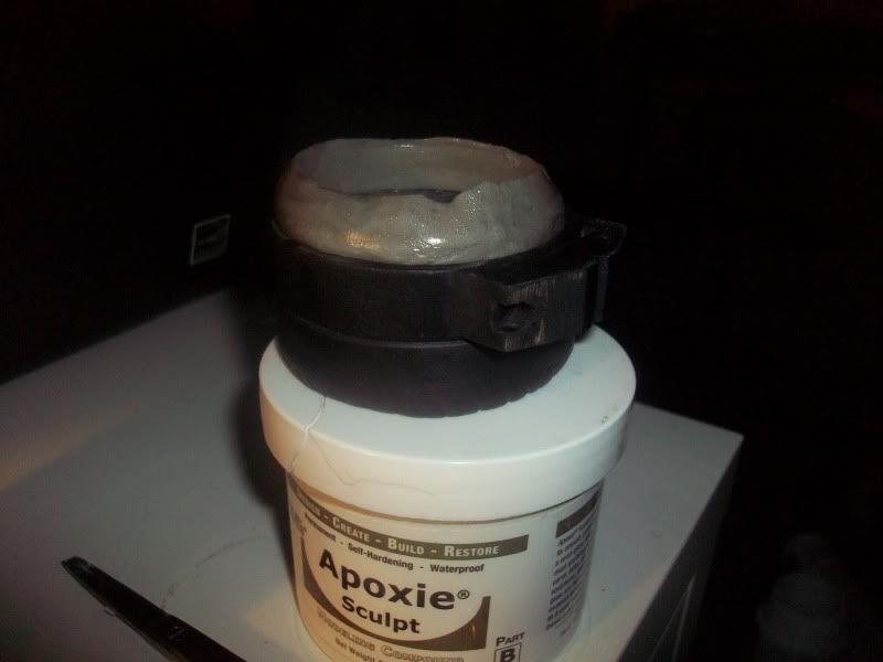
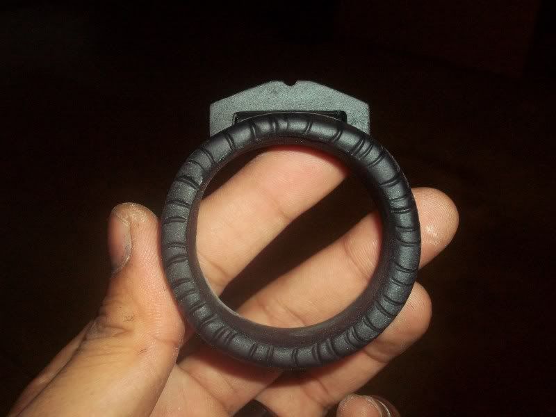
Building up the last remaining ring of the rear endcap. Basically, I mounted the second and third rings onto a scrap piece of aluminum tubing that I slathered with Vaseline. After that, I mixed up a bit of AS and squished it onto the tubing, forming another ring. Then, the whole deal was pulled off the tubing so I could smooth the inner surface and ensure the AS ring would properly adhere to the second ring.
I threw everything back onto the aluminum tubing so I could start shaping the AS ring. I took the first ring and smooshed it right on top. When it looked like everything was nice and symmetrical, I smoothed everything out with my sculpting tools.
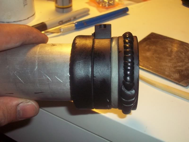
After the AS ring cured, I sanded it entirely with 220 grit until the ring was all the same thickness. Then the AS ring was JB Welded to the first ring. I hit it with some flat black so I could visualize all the trouble spots.
Finally, I drilled in all the functional mounting holes and the non-functional mock holes (such as these two). The only work left to do on this section of the gun is to shave down the back end of the aluminum tubing 1/4" so it doesn't jut out, and then make some sort of cover to hide the back end of the grip plug when everything's mounted. Other than that, the rear endcap is DONE.
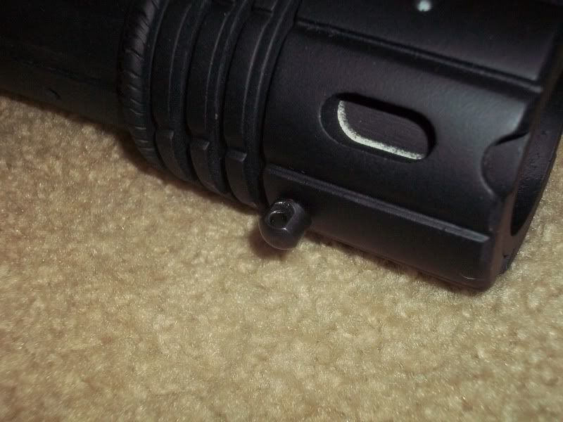
And finally, the answer to the question I asked at the beginning of the post. The piece in question is a bipod mount that I found on the YHM website...the exact piece used on the original!

Just so you have a better idea of the gun's scale, I'm 5'8".
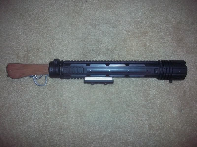
And here's everything all together. At this point, the blunderbuss is FINISHED. This is how the gun looks when it's fresh out of the package. The next few days will involve me finishing up all the odds and ends, screwing everything together, and then weathering the eff out of it.
Thanks for following, guys!
-Jonaas
After a couple podcasts worth of work, it's time for a HUGE pic update!
Who knows where THESE suckers go? Hint: They're the ONLY metal parts that I'm including in the resin blunderbusses. Find out at the end of this post!
After getting the grip of the slide nice and smooth, I went about detailing it. First, I plotted out the relative placement of everything with a Sharpie.
The holes I'm using to mount the grip to the slide base were already pre-drilled.
I roughly sculpted on the "nubs" of the grip with Apoxie Sculpt and used my Dremel and a round file to cut in the notches.
After the Apoxie Sculpt cured, 220 grit sandpaper was used to clean everything up and make it nice and smooth. Gaps were filled with Bondo Spot Putty.
Finally, a shot of flat black to see how it all squared away.
This piece has since been further altered, as the "nubs" have a more rounded edge to them. I still need to find the proper screws to mount the slide grip to the slide base, but other than that, this slide is 100% DONE.
A shot of the final trigger mechanism. It took a lot of doing, but it works FLAWLESSLY. However, even though I'm extremely happy with how it came together, I think I want to remake the entire wooden grip frame and grip plug out of aluminum. Essentially, I would have to cut out the "spine" of the grip frame out of 3/8" thick aluminum sheet and then sandwich the spine with a 1 3/4" aluminum rod that's been split in half. After those pieces are secured together, I'll need to cut out all of the recesses for the spring and trigger AND tap the mounting holes. Is there anyone out there with good tools and machining skills who could do this for me? Seriously, I'll either give you a free slushcast blunderbuss or solid resin blunderbuss parts in return for your work. PM me if you can!
Building up the last remaining ring of the rear endcap. Basically, I mounted the second and third rings onto a scrap piece of aluminum tubing that I slathered with Vaseline. After that, I mixed up a bit of AS and squished it onto the tubing, forming another ring. Then, the whole deal was pulled off the tubing so I could smooth the inner surface and ensure the AS ring would properly adhere to the second ring.
I threw everything back onto the aluminum tubing so I could start shaping the AS ring. I took the first ring and smooshed it right on top. When it looked like everything was nice and symmetrical, I smoothed everything out with my sculpting tools.
After the AS ring cured, I sanded it entirely with 220 grit until the ring was all the same thickness. Then the AS ring was JB Welded to the first ring. I hit it with some flat black so I could visualize all the trouble spots.
Finally, I drilled in all the functional mounting holes and the non-functional mock holes (such as these two). The only work left to do on this section of the gun is to shave down the back end of the aluminum tubing 1/4" so it doesn't jut out, and then make some sort of cover to hide the back end of the grip plug when everything's mounted. Other than that, the rear endcap is DONE.
And finally, the answer to the question I asked at the beginning of the post. The piece in question is a bipod mount that I found on the YHM website...the exact piece used on the original!
Just so you have a better idea of the gun's scale, I'm 5'8".
And here's everything all together. At this point, the blunderbuss is FINISHED. This is how the gun looks when it's fresh out of the package. The next few days will involve me finishing up all the odds and ends, screwing everything together, and then weathering the eff out of it.
Thanks for following, guys!
-Jonaas
Last edited:
FakeBritishAccent
Sr Member
Re: Looper Blunderbuss - WIP pics begin on Page 3
Thanks for all the kind words, guys. Now that Step 1 is almost over, let's hope Step 2 (molding and casting YOUR blunderbusses) goes just as easily and successfully.
There's a really good reason why I'm not collecting any of the deposits just yet. Like I mentioned before, a pretty big production company is using my blunderbuss in their Looper parody on Friday. Though they're insuring the blunderbuss and I'll be on set at all times to monitor the gun's use and make sure it's not roughed up, there's still a chance the gun can be damaged. If that happens, I'll need time to patch it up before molding. I don't want to collect any money until I KNOW that the blunderbuss is 100% ready for the run.
Nevertheless, if all pans out, I'll be asking for the First Run's deposit between October 22nd and November 7th, so keep an eye on your Messages folder then.
I spent about thirty minutes sculpting on a few small details on the rear endcap. After that I realized there's really nothing left for me to do tonight. I don't have all the hardware I need to assemble the gun nor do I have all of the paint I need to weather it. Tomorrow, I'll pick that stuff up, as well as a roll of hockey tape.
-Jonaas
Thanks for all the kind words, guys. Now that Step 1 is almost over, let's hope Step 2 (molding and casting YOUR blunderbusses) goes just as easily and successfully.
Take my money now!!!
There's a really good reason why I'm not collecting any of the deposits just yet. Like I mentioned before, a pretty big production company is using my blunderbuss in their Looper parody on Friday. Though they're insuring the blunderbuss and I'll be on set at all times to monitor the gun's use and make sure it's not roughed up, there's still a chance the gun can be damaged. If that happens, I'll need time to patch it up before molding. I don't want to collect any money until I KNOW that the blunderbuss is 100% ready for the run.
Nevertheless, if all pans out, I'll be asking for the First Run's deposit between October 22nd and November 7th, so keep an eye on your Messages folder then.
I spent about thirty minutes sculpting on a few small details on the rear endcap. After that I realized there's really nothing left for me to do tonight. I don't have all the hardware I need to assemble the gun nor do I have all of the paint I need to weather it. Tomorrow, I'll pick that stuff up, as well as a roll of hockey tape.
-Jonaas
MFP 2020
Sr Member
Re: Looper Blunderbuss - WIP pics begin on Page 3
This is fantastic. Well done, sir!
Now, if you'd allow me to be petty for a moment...
...this is a sling swivel stud. (But yes, they can be used to mount bipods as well.)
OK, sorry. I'm just a stickler for proper nomenclature. I love your work!
This is fantastic. Well done, sir!
Now, if you'd allow me to be petty for a moment...
And finally, the answer to the question I asked at the beginning of the post. The piece in question is a bipod mount that I found on the YHM website...the exact piece used on the original!
...this is a sling swivel stud. (But yes, they can be used to mount bipods as well.)
OK, sorry. I'm just a stickler for proper nomenclature. I love your work!
FakeBritishAccent
Sr Member
Re: Looper Blunderbuss - WIP pics begin on Page 3
No worries, sir! Thanks for the correction and for the kind words!
-Jonaas
OK, sorry. I'm just a stickler for proper nomenclature. I love your work!
No worries, sir! Thanks for the correction and for the kind words!
-Jonaas
FakeBritishAccent
Sr Member
Re: Looper Blunderbuss - WIP pics begin on Page 3
Updates!
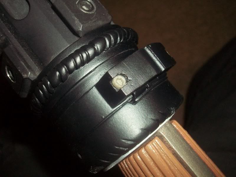
I used a teeny, tiny bit of Apoxie Sculpt to make the sight's screws. I basically mashed in the clay, used a small Allen wrench to detail it, and then sanded it to shape. If it didn't mean having to special order parts, I would've just used the appropriately sized actual screws...but I'm happy with my results.
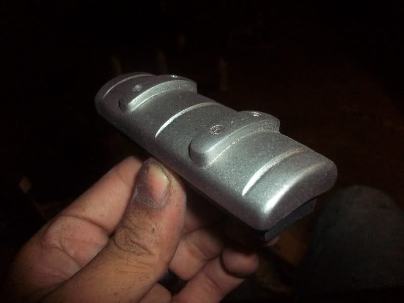
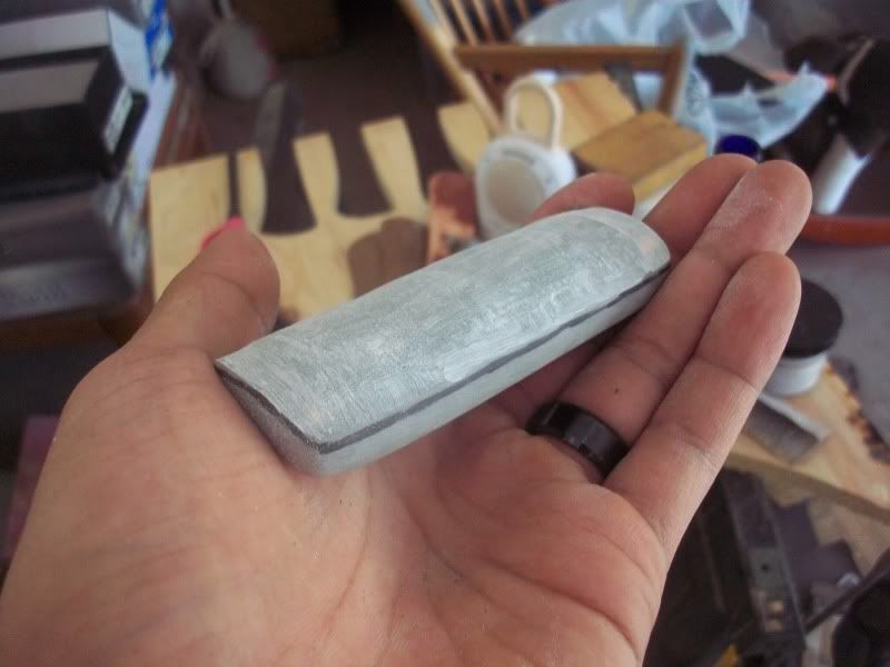
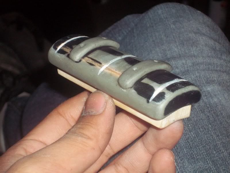
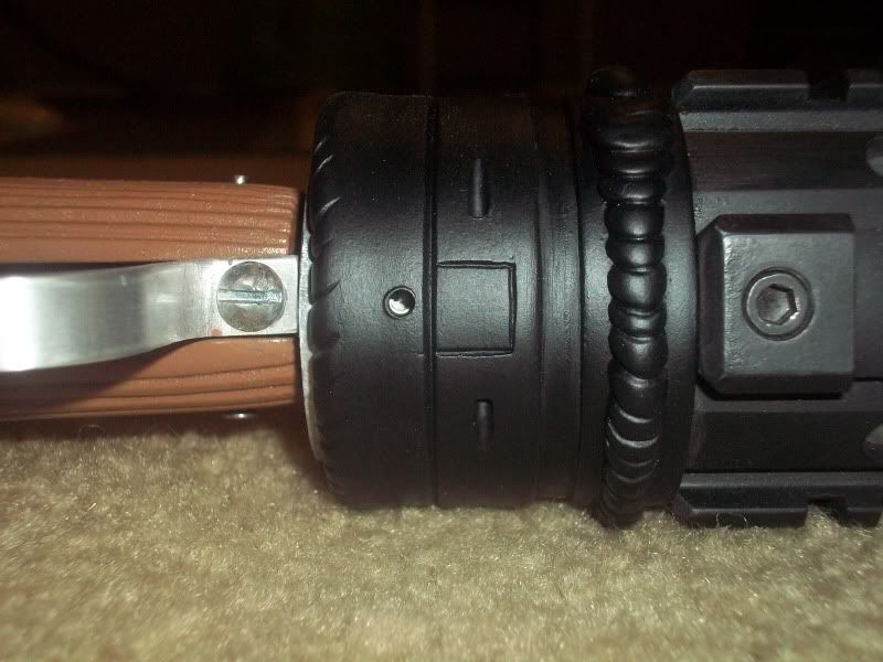
I gave the slide grip a coat of stainless steel. This is NOT the final color, but I just wanted to see if it looked like it could be machined out of metal.

Finally, I tapped holes in the slide/slide grip to fit some small cap screws. These screws secure the slide grip to the slide base. Unfortunately, the heads of the screws were a bit too big for the holes I drilled, so I ended up splitting some of the clay detailing. I've since thinned out the screw heads and repaired the cracks with more Apoxie Sculpt.
While that's curing, I have to extend the grips about 1/4" to make up for some trimming I made to the grip plug.
So that's that, for now! Thanks, everyone!
-Jonaas
Updates!
I used a teeny, tiny bit of Apoxie Sculpt to make the sight's screws. I basically mashed in the clay, used a small Allen wrench to detail it, and then sanded it to shape. If it didn't mean having to special order parts, I would've just used the appropriately sized actual screws...but I'm happy with my results.
I gave the slide grip a coat of stainless steel. This is NOT the final color, but I just wanted to see if it looked like it could be machined out of metal.
Finally, I tapped holes in the slide/slide grip to fit some small cap screws. These screws secure the slide grip to the slide base. Unfortunately, the heads of the screws were a bit too big for the holes I drilled, so I ended up splitting some of the clay detailing. I've since thinned out the screw heads and repaired the cracks with more Apoxie Sculpt.
While that's curing, I have to extend the grips about 1/4" to make up for some trimming I made to the grip plug.
So that's that, for now! Thanks, everyone!
-Jonaas
Brick Bronson
New Member
Re: Looper Blunderbuss - WIP pics begin on Page 3
All ive got to do to finish my Babys First Blunderbuss is find something to act as rails on the top, and i dont feel like using a garden hacksaw to cut a piece out of a pvc pipe.
All ive got to do to finish my Babys First Blunderbuss is find something to act as rails on the top, and i dont feel like using a garden hacksaw to cut a piece out of a pvc pipe.
FakeBritishAccent
Sr Member
Re: Looper Blunderbuss - WIP pics begin on Page 3
You could try 6mm craft foam. You'll still have to cut out each "tooth" of the rail, but it'll be alot easier than cutting it out of PVC. Just cut a 1" thick strip about a foot long and then cut it into 1"X1/4" rectangles. Then, glue each one in a strip onto your blunderbuss!
Good luck, Brick!
-Jonaas
All ive got to do to finish my Babys First Blunderbuss is find something to act as rails on the top, and i dont feel like using a garden hacksaw to cut a piece out of a pvc pipe.
You could try 6mm craft foam. You'll still have to cut out each "tooth" of the rail, but it'll be alot easier than cutting it out of PVC. Just cut a 1" thick strip about a foot long and then cut it into 1"X1/4" rectangles. Then, glue each one in a strip onto your blunderbuss!
Good luck, Brick!
-Jonaas
Similar threads
- Replies
- 10
- Views
- 1,122
- Replies
- 25
- Views
- 2,783