Daft Punk Thomas Helmet -- Skipped a few chapters

Just curious, on a scale of 1 to 10, how insanely hard would this type of electronics work be for someone who only knows how to solder an LED to a switch and battery?

I'll be embarking on my own Daft Punk helmet project (both of them), and the electronics are scaring me to death. I'll at least be making static/non-lit helmets, but what's a DP helmet without electronics?

I'll try to refrain from asking you a bunch of stupid questions whenever I get to the electronics point (I'll be studying this thread extensively). :thumbsup
 
It looks fantastic mate! and this thread is awesome im just starting to make this from pep, it will be the first project like this I have ever done so huge thanks for the info here :)
 
Thank you for taking the time to document this most excellent build. [/BillAndTedVoice]

I'm a newb here w/nothing published yet, but still feel compelled to pass on my gratitude and thank you for this really outstanding work and sharing.
 
I'll take a brake from the matrix build as I wait for a few components. Now, it's time to work on the side LED boards. Since I'm not really savvy with doing PCBs yet, I'll tackle this with Prototype board :confused

(I will later post a schematic showing the connections as they can get tricky)

Since Volpin is using PCBs which is the "whole Enchilada", I decided to do a "Double Decker" instead :lol .... can you tell I'm hungry?

Anyway, just stay with me...

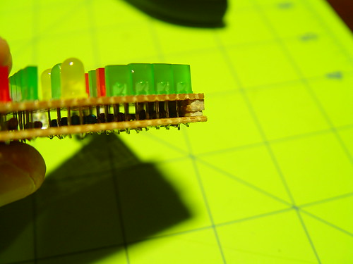
This is a little trick I used while building the electronics for my Guy Manuel helmet. Basically, I used 2 layers of perf board. The bottom layer will be used to place components that you don't want people to see OR when components are really close to each other.

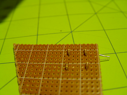
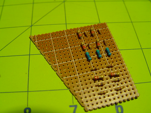
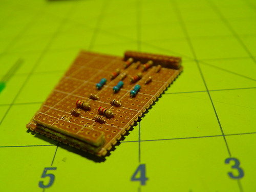
So, the first bottom layer consists of resistors only. These will later be hidden by the top layer.

5810874628_540b7b7b04.jpg

5810309243_72e643dcbc.jpg


5810874488_7cb4346981.jpg


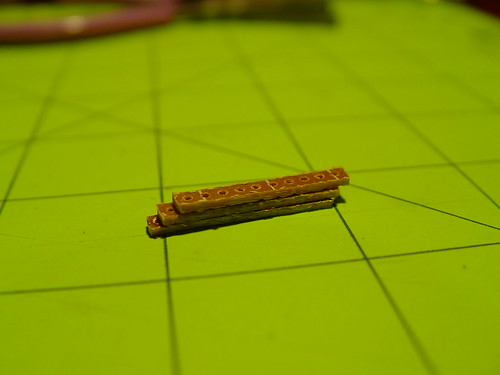
After finishing the bottom layer, I then glued these little walls of the same material thickness.
5810874900_c92f4b31e5.jpg


Like so..
5810875244_269862bf50.jpg


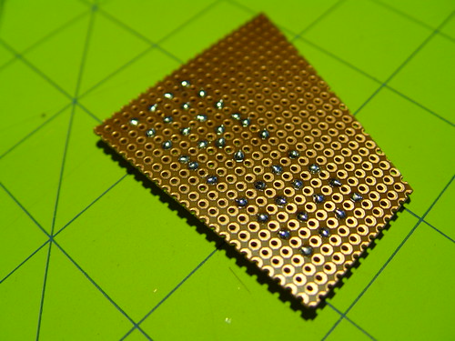
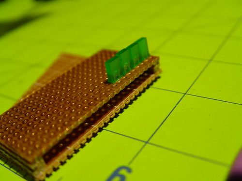
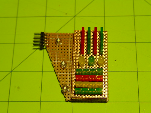
Then it was time to put the top layer while hiding those resistors underneath.

5810875534_08f1dcd206.jpg


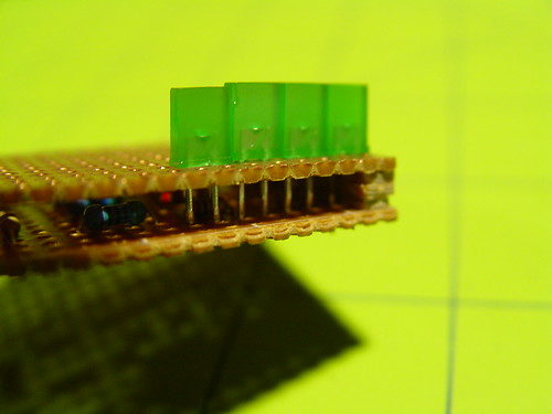
Another advantage of this method is that it brings the uncovered LEDs to the front and leaves the LEDs that will later be covered with colors gels behind. Giving them more room to diffuse the light.

5810875392_be353d0124.jpg


Notice how clean it looks without resistors
5810876032_d56c9a685a.jpg


5810875660_04db8e8273.jpg


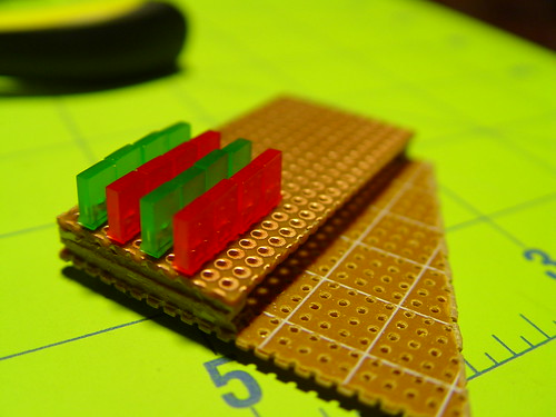
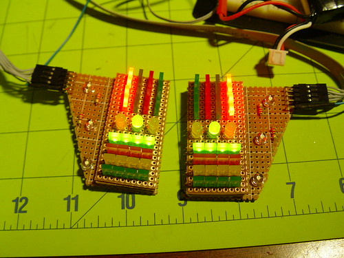
All components in place.

5810310271_641ba9663f.jpg


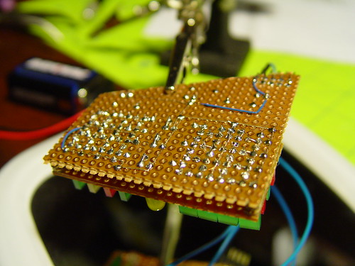
Now for the fun part :confused

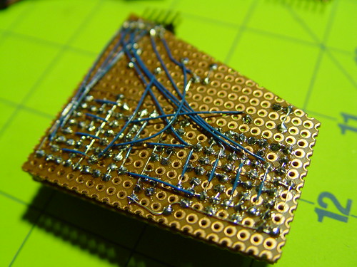
Start running traces to connect these components.
5810877736_212aa08912.jpg


Wow!!! What a MESS..

5810311527_faba8182be.jpg


I wonder if this will even work...:confused

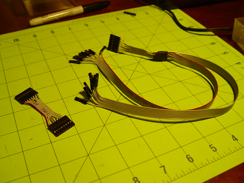
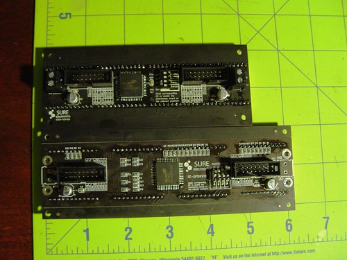
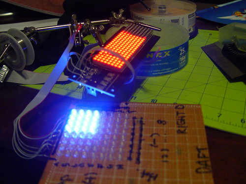
Using ribbon cable, I made the wire harnesses from the Led chaser to the transistor board to the LED boards.
5810876534_8c2e5d4cd4.jpg


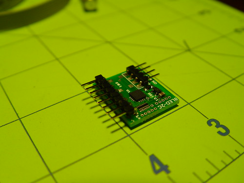
This little guy is the brain power
5810311779_62d34c1913.jpg


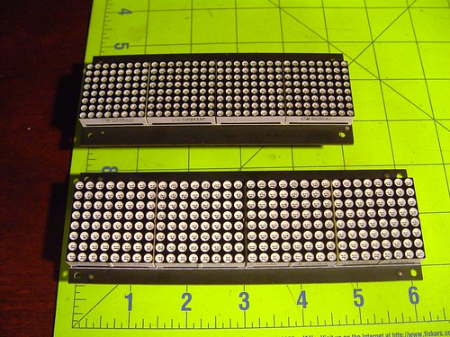
Here are the basic components of the side boards. I still need to do another board mirror of the one shown here.
5810311197_bb2496eb5f.jpg


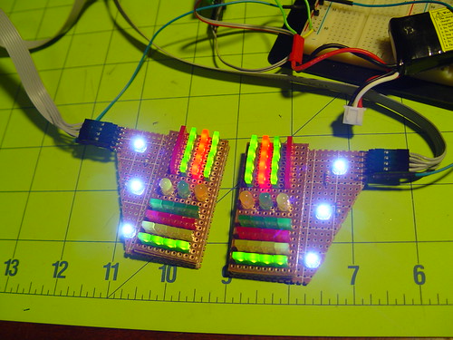
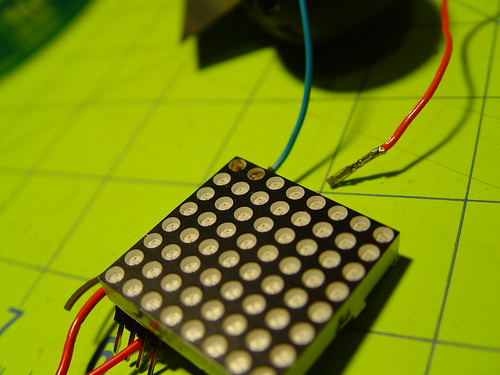
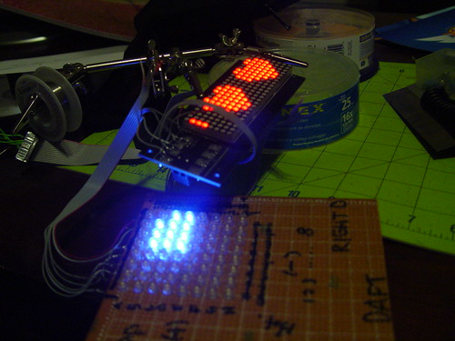
I connected everything and tested the pins with a battery before introducing the chaser and transistor board.
5810312783_7658d34a94.jpg


Then it was time!!!! After some preliminary tests.... this is how I felt (link)

5810312435_37fa306917.jpg


Here's a video of the lights in action...

:love YouTube - ‪Daft Punk - Thomas Bangalter - Helmet Side Boards‬‏


one step closer...


I was just wondering where the schematic you said that you would post is. I would like to know the resistors that you used as well as the wiring setup.

Second. Where can i find the sequencer that you used.

How did you program it (if you did)

8 Channel PWM LED chaser

I found this and was wondering if I could build it and then you had the code for your chaser you could upload? (and show us how to download it to the chip :p)

What exactly does each part do. (From the battery to the chaser, to the transistor board, to the actual units)

What does each part of your batter pack do. I noticed 2 switches and a small odd looking black cube on it. Is it possible to use removable batteries and how?

Where did you get those flat LED's from?

Sorry for all the questions, it seems that the electronics seem a little bit more involved for this part.

There are probably many more to come :-/
 
@shween Sorry for the late response, but hopefully this will help.

"Where can i find the sequencer that you used."
The LED chaser can be purchased by sending an email to Donnie (donniedj@anothercoilgunsite.com)

"How did you program it?"
I didn't. Donnie does the programming. All you do is tell him what patterns you want programmed. Go to the bottom of this page for links to all the available patterns.
Plasmado Projects


"I found this and was wondering if I could build it and then you had the code for your chaser you could upload? (and show us how to download it to the chip :p)"
I'm sure you can use this, but since I don't hold the programming of the chasers I'm using, I cannot be of any help. That's why I'm using the chasers from Donnie because he has done all the programming, and he offers a wide variety of patterns.

"What exactly does each part do. (From the battery to the chaser, to the transistor board, to the actual units)"
I would suggest reading this tutorial Plasmado Projects
In a nut shell, the chasers don't have enough 'juice' to run many LEDs, so the transistors are used as switches. The Chaser provides the signals to the transistors for switching and the LEDs get the full RAW power from the battery pack not the chasers.


"What does each part of your batter pack do. I noticed 2 switches and a small odd looking black cube on it. Is it possible to use removable batteries and how?"
One switch controls power to the main LED matrix while the other controls power to the side boards. They're independent of each other. I could have wired everything to one switch, so it is simply personal preference.
Since there are two independent switches, I have two independent power cables. That 'cube' you're referring to is nothing more than two 1x3 connector housings glued together. In my application, my LIPO batteries can be removed by simply disconnecting the power controller. You can easily use a project box and fit 6xAA batteries if you want.


Where did you get those flat LED's from?
I bought mine from Ebay. Just do a search for "2x5x7 Rectangle LED"
 
I've been lurking and find your method of mounting the LEDs genius, and the use of your controller board very creative and awesome, but a LOT of work.

My only concern in your method is that you might only be able to use the SureElectronics board to drive the LEDs of the same color that the board came with when you hack/remove them off. This is because the board is designed to drive, for example, red LEDs, with a forward voltage of 1.6V.

Adopters of this method should be warned that if you try this exact method with blue or white LEDs, it might not work. The Arduino nano board certainly would work, but you would need something else to take the Arduino logic and parse it up to your LED array, which is really what you are using the SureElectronics board for. White and Blue LEDs have forward voltages > 3.4V.

Any other color, you should be good. But I noticed this when starting my Tron Legacy Guy Manuel build, which has a band of Thomas like LEDs across the helmet that certainly are either blue or white.

Another note of concern: you really want to avoid letting the PETG material get much UV exposure, or it will start to yellow on you. Not a concern probably on the died part, but in your inner visor, would bug me I guess.

I admire the efficiency of the method, and the results are awesome. Keep up the awesomeness!
 
Last edited:
Just curious, have you tried to build a full array with white LEDs using the Red LED SureElectronics board?

You are correct that different colored LED will have different forward voltages. However, the reason for my question is because before doing a full blown matrix of red LEDs, I did some preliminary trials and tested one panel made up of an 8x8 matrix of white LEDs and gave me the same results via the naked eye approach.

In other words, the LEDs in your matrix may be a bit brighter or dimmer depending on the SureElectronics board used and the LEDs used in the external matrix, but not to the point that the difference is noticeable.

Certainly not to the point where they won't work because I do have a 5mm Red SureElectronics board and have tested it with white LEDs and they do work. Now perhaps you're using a 3mm Red SureElectronics board to a 5mm white LED matrix.

My best advice to anyone is to test your equipment, do trials, etc. before launching a massive effort.
 
I edited my post, I didn't realize till later how strong my language was. I was doubting it would work, but if you tested it and say it works, well I'll give it a shot. The answer to your question is no, I haven't started building, but I really want to get to it after reading your thread. Thanks for the insight
 
I edited my post, I didn't realize till later how strong my language was. I was doubting it would work, but if you tested it and say it works, well I'll give it a shot. The answer to your question is no, I haven't started building, but I really want to get to it after reading your thread. Thanks for the insight

No problem. I just hope it is clear that is not a matter of who is right or wrong, but rather providing solid information that others can leverage.

I just had to challenge your initial comment a bit because I had tested the same scenario with positive results. If left unattended, that would have swayed people away from this approach.

On a different note, I do have a 3mm Red SureElectronics board that I will be testing in the near future using the same single 8x8 panel of white LEDs. Once I get to that point, I'll report the results.

In total agreement, which is why I edited it. Keep up the good work. I'll let you know how my implementation goes
 
Well, apparently I don't know the difference between a 5mm and 3mm LED. :confused

It seems like the board I originally had was a 5mm board making it longer than the new 3mm LED board I received. Along with that, there has been an upgrade on the chip.

To summarize:

  • Seems like SureElectronics has upgraded their chip from HT1632 to HT1632C. If you get a new board, use Andyval's code. If you have the old chip board, then use my code.
  • There is a 5mm and 3mm board available with the 3mm (top) being the shorter one of the two shown below

    6307193175_d32c694cef.jpg
6307193357_d2d264c2a1.jpg


  • The 3mm board is a better fit for the helmet (space saver), but it has some resistors between the LED panel and the actual board increasing the risk of damaging the components as you saw the connectors to detach the panels. A better approach for detaching the panels is to desolder the panels using a desoldering pump or braid. Painful? Yes, but a sure way to avoid damaging components.
  • The old 5mm board has all of the components on the opposite side making it safe to use a saw to cut the panels. However, the board is longer.
    5827286132_64d8d0c761.jpg

So I ordered myself a 3mm board for this project, and just curious why you mention different code than yours should be used? And could you post a link to the code you speak of that works better for the 3mm board? Thanks
 
Getting close to embarking on this method for my helmet, got the code working in my 3mm LED board, yay. I notice no mention of how you formed the PETG into the visor shape. Whats the magic behind this? You said that when you put it in the boiling water it acted like paper. Do you like soak it really hot, then as it cools does it harden in place and take shape? Could I use a hair dryer to blast it with hot air to make it mold?
 
Getting close to embarking on this method for my helmet, got the code working in my 3mm LED board, yay. I notice no mention of how you formed the PETG into the visor shape. Whats the magic behind this? You said that when you put it in the boiling water it acted like paper. Do you like soak it really hot, then as it cools does it harden in place and take shape? Could I use a hair dryer to blast it with hot air to make it mold?

My visor was never formed to the shape of the helmet in its resting position. Since the PETG is flexible, I could bend it and while it was trying to flatted it would bump against the cavity that I carved from the inside of the helmet.

It was a tight fit that I didn't even have to glue it to the helmet.

Volpin on the other hand, DID bend his visor to the shape of the helmet in its resting position. I believe he did it by placing the visor in a buck of the shape of the helmet, then strapped it and used a heat gun.
 
No problem. I just hope it is clear that is not a matter of who is right or wrong, but rather providing solid information that others can leverage.

I just had to challenge your initial comment a bit because I had tested the same scenario with positive results. If left unattended, that would have swayed people away from this approach.

On a different note, I do have a 3mm Red SureElectronics board that I will be testing in the near future using the same single 8x8 panel of white LEDs. Once I get to that point, I'll report the results.

Well I finally got my parts in, with a 5mm white LED and a 3mm SureElectronics board. I'm sad to say that using your matrix decode of the row and columns from the board, I can't get the LED to even ignite. I tried using the whole row drive (like row A, connecting the (-) to ground), it worked, but very dimly. Now its possibly important to note that I haven't unsoldered the array that came with the board, and the board I"m using is a 3mm green, not red. Do you think the 5mm board makes all the difference? I don't want to buy one just to find the same problem out. Thanks
 
Well, don't get discouraged my friend, and I'm sorry you're not having luck. I have been there plenty of times without any sort of guidence which is why I always gave people warning that if I got stuck, then others following would be stuck too. :$

Let's also acknowledge that you have deviated from the materials I used in my implementation. I used the older style HT1632 SureElectronics with 5mm Red LEDs. and you're using a new style HT1632C with 3mm Green LEDs.

Moreover, I can assure you that if you're trying to test an LED with the panel still attached to the board, you will see a major degragation in brightness as you are running 2 LEDs in parallel at that point.

So, you must take the panel out to see the true brightness of a single LED within the matrix.

With that in mind, I have some GOOD news and some BAD news.

The BAD NEWS is that SureElectronics changed the mapping in the new HT1632C 3mm Red board. I don't know if the change happens because is a new chip OR if it's because of the 3mm size. However, I have done some preliminary tests and I can see that the mappings are different. I'm in the middle of decoding it, so I don't have the full mapping yet.


The GOOD NEWS is that:
  1. It's just a matter of time before I can decode the mappings, and you'll have a functional board again.
  2. It is possible to drive a 5mm white LED with the 3mm Red SureElectronics board (haven't tested green, but I'm sure it will be fine). This puts to rest the uncertainty we had in the past if a 3mm matrix board could drive white 5mm LEDs. So, the answer is YES! :love
It's really late and got to get some sleep as I'm making stupid mistakes. Here's the evidence.

6867924655_09e1217eca.jpg


Just blew a few LEDs as I forgot to put a resistor. :facepalm


Here's the proof of concept using a 3mm board with 5mm LED matrix while decoding the new mapping.

6867924473_7ba0ffe036.jpg


6867924225_126e3372b3.jpg


More to come... stay tunned. :thumbsup

Well I finally got my parts in, with a 5mm white LED and a 3mm SureElectronics board. I'm sad to say that using your matrix decode of the row and columns from the board, I can't get the LED to even ignite. I tried using the whole row drive (like row A, connecting the (-) to ground), it worked, but very dimly. Now its possibly important to note that I haven't unsoldered the array that came with the board, and the board I"m using is a 3mm green, not red. Do you think the 5mm board makes all the difference? I don't want to buy one just to find the same problem out. Thanks
 
My friend, thanks for helping me to be assured the white LEDs will work. And for figuring out the pattern in the 3mm board is different. And for doing the hard work for us and figuring out that pattern. I look forward to your results, thanks man!
 
This thread is more than 7 years old.

Your message may be considered spam for the following reasons:

  1. This thread hasn't been active in some time. A new post in this thread might not contribute constructively to this discussion after so long.
If you wish to reply despite these issues, check the box below before replying.
Be aware that malicious compliance may result in more severe penalties.
Back
Top