Daft Punk Thomas Helmet -- Skipped a few chapters

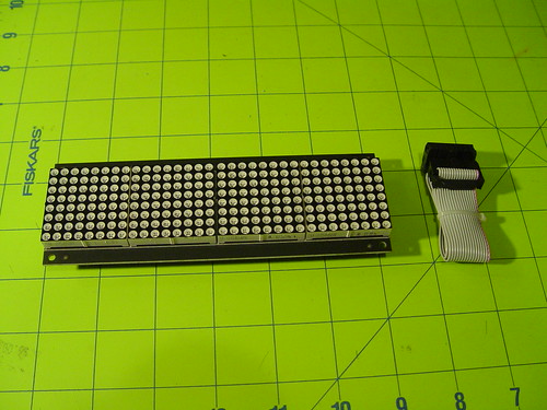
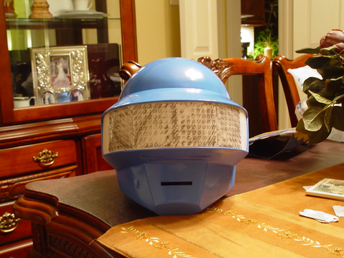
Since, I'm going with an 8x32 Matrix, I wanted to quickly visualize the footprint of the matrix relative to entire visor area based on a .1" spacing.

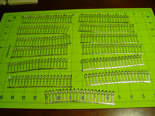
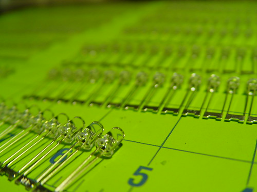
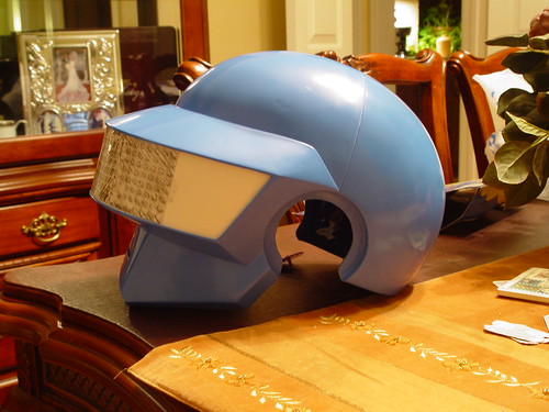
I grabbed an old prototype board. Placed 64 flat top 5mm LEDs and traced an 8x8 grid. It was quick and dirty - trust me. I then photocopied the traced area 3 times. Cut the squares and taped them next to each other. I then taped this strip onto the temp posterboard visor. Now, I can more less visualize what people may see of the matrix from different angles.

I'll probably do a more accurate one, but for now this 10min approach will suffice.
5611715841_5b7d33b189.jpg

5611716031_b2e8a22901.jpg

5611716205_db0c02eb17.jpg
 
I'm loving this! just a heads up before you chrome it, there seems to be a small dent on the cheek bone area(left in pic, right in real life)
 
I'm loving this! just a heads up before you chrome it, there seems to be a small dent on the cheek bone area(left in pic, right in real life)

Unfortunately, they all do that. It is the result of a small air bubble trapped behind a registration key in the mold. There's a few other places where the helmet has similar small marks, which is why I recommend a quick pass of sanding and a little filler before chroming these buckets.
 
Got my 8x32 LED Matrix from SureElectronics. Nice little package I must say.
5628665602_3a757bfd9d.jpg

5628082737_9e285070df.jpg

Compiled the given code, uploaded it to my Arduino, and gave it a test run.
Whoa!!!! It worked!! :love

First thing I noticed is that the animations are not played sequentially. They're basically picked at "random". <<My wife made a comment that random functions are not really random and the algorithms behind them normally follow patterns>> I know she's right, plus I want more control over what gets displayed. So, I made a few mods to the code, and now I got it to display all 14 animations sequentially.

Take a look.
YouTube - Arduino & 8x32 Matrix from SureElectronics

Ah..yeah, I also changed one of the messages to display my nick "tekparasite" just for Fun. It's easy to change in the code, so it was no biggie.

more to come..
 
Now for the controls portion of this project. Options?

As most of you know, Volpin is going all out! He's skipping wires entirely and doing a wireless (WiFi) solution complete with iPhone app interface. As much as I like the idea, that's too far out there for my reach :(

Instead, I'm going in the opposite direction and downgrading the technology. Okay, maybe not to the level where I'll be using strings, pulleys and gears, but I'm going ANALOG.

Here's what I'm thinking. In a practical sense, people will look at me (the helmet) and respond with.. "That's cool!!" or "Awesome man!!" or something similar. In the same way, I want to be able to display a generic response quickly in the matrix with the usual "OK" or the like.
If I see a cute lady or group of ladies, I would like to display the 3 heart shape animation.

In short, I want to be able to select certain animations on demand and/or have a setting where they play sequentially.
So, I'll be using this:
5628666882_0110766905_m.jpg
5628084045_64d260a36a_m.jpg
5628667518_3cac6f84dd_m.jpg

It's a 5-position switch. My plan is to make Position 1 be default and will play all animations sequentially. Position 2-5 will be pre-selected animations out of the 14 available. Any selected animation (2-5) will be played continuously until I switch to a different position or take it back to default (position 1).

This implementation will be so useful later. If I'm walking around and need to improve my visibility, I'll select a less intrusive animation. If I'm standing still or sitting down, then I'll crank it up full blast to display all LEDs... etc.

PROBLEM:
This is a switch, not a potentiometer! After searching online for a potentiometer with hard stop positions and coming out empty, I decided to convert this switch to act as a potentiometer that Arduino can read.

More on that later.
 
Last edited:
That is so awesome! I wish I could figure out how to rig up something like that. At this point I don't think I'll be able to put lights in my helmet at all.
 
Before I get ahead of myself, I wanted to share with you some helpful information and links for those that want to follow this implementation.

WARNING: I really don't know what I'm doing, so if I get stuck, you'll be stuck too. So, proceed at your own risk. :lol

Let's continue, shall we?

ARDUINO:

  • Buy the hardware. I'm using the "Duemilanove" version for now, but my plan is to use the "Nano" version in the final piece.
  • I'm not going step-by-step here, but download the software and make sure you know how to compile and run. At a minimum, you should be able to run the "Hello World" and/or the "Blinking Light" examples.
  • Here's the code base for the animations as you saw in the video from my previous post.
    http://www.plasmado.com/pro3/ThomasV2.zip
Sure Electronics


Now, below are the connection instructions.

  1. Looking at the display from the back (logo facing right side up), connect the flat ribbon cable to the right port. It's keyed, so there is no way to mess this up
  2. Make sure dip switch 1 is ON while leaving the rest in the OFF position.
  3. Extend the flat ribbon cable without turns or kinks so that the connector faces you. Notice that the 'keyed' side should be on top while the flat side on the bottom.
  4. Looking at the diagram below, make the connections between your Arduino and the Matrix connector.

    5629675119_75f35dd2ce_o.jpg
 
only question is are you going to be able to see out of the helmet?
Of course, I have x-ray vision. :love
Just kidding. Good question though. I don't know if you guys have realized, but I plan to hack the crap out of that SureElectronics module. Remember I said, I may fall flat on my face? Well, seems like I'm heading that way. We'll see, just stay tuned for a good laugh or be amazed.

That is so awesome! I wish I could figure out how to rig up something like that. At this point I don't think I'll be able to put lights in my helmet at all.
I'll provide as much info as possible. I'll try anyway.

The LED effects look awesome, but wont it be weird when the display is flat and the visor is a semicircle?
Yes. I'll figure something out. I'll bend it or something. :lol
 
Sorry guys for the continued spamming..
Now, back to the 5-position switch. So, I know Arduino can read via a potentiometer (pot). A pot is nothing more than a voltage divider using resistance. As you move the pot knob, you change the resistance. So, to simulate this, I'll be using resistors.

A typical unit would be a 100K Ohm Potentiometer. In a 5 position switch, I'll need 4 resistors connected in series in between each pole.
So, 100/4 = 25 or 25K Ohm. I couldn't find the exact one, so I bought 22K Ohm. No worries, that would work.

Here's the diagram.
5629794737_7bf07293d4_o.jpg


... and here's how I soldered them.
5628667876_d5583e2755.jpg

5628668148_b69bfca9bb.jpg

5628668410_9aab2ed1d8.jpg


So now, I have 3 leads coming out of my switch: +5V, GND and Variable.
Here's how I connected them to my Arduino.
Arduino - Potentiometer


I modified the code to read the values of this POT and Whoa!!!!

It worked!!!!

Position 1 - Plays all sequentially
Position 2 - Eyes
Position 3 - OK
Position 4 - Hearts
Position 5 - Daft Punk (black background).

Of course, I can re-program each position to display the animation of my desire. :cheers
 
Last edited:
After getting some PET sheets in the mail, I was able to fit the visor. Even after measuring and re-measuring, I still had to do some minor adjustment cuts for a good fit.

The PET is crystal clear, I just left the protective film on both sides as I'm handling it quite a bit so to avoid scratches.

5628668746_a2d5c04944.jpg


I'm still trying to figure out how I'm going to keep the visor in place on a more permanent basis to prevent movement yet have the ability to take it out if I need to.

As you can see, the visor is fed from the inside.

Now, this is what I'm planning on using for a sub-visor. The reason why I'm not using the same PET sheet as in the visor is because this piece is already curved in its resting position. Luckily, the curvature matches perfectly with that of the helmet, so I can safely say..WINNING!

5628085799_3c952051e8.jpg


[[ EDIT ]] Oh Wait.. I forgot to include this update. A sea of LEDs!!
5628082961_9c876b424b.jpg
5628083289_3ca0f8e3bb.jpg
 
Last edited:
Now is time for some tinting.

I started by getting the biggest stockpot I could find at "Mal-Wart" :lol.
I found this 21 quart capacity pot. I don't think I needed this big of a pot, but I was also planning on tinting my guy manuel visor.
5662842825_56997b5925.jpg


Anyway. First, I filled the pot to about 3/4 full ,and set the temp at 160 deg F.

Once the water reached that temp, I poured the dye. I used 4 packs
5662843205_fc0826e372.jpg


Rigged the visor with a clothes hanger for an easy way to pull it out, and in it went for its first dip.
5663411632_e8b75198c6.jpg


It only took 10 seconds to realize the water was too hot for the thin PETG sheet. It was basically floating like a noodle. :confused

5662843809_0331ca9f45.jpg


I did see, however, how the dye was adhering to the plastic.

After a few trials, I noticed that 140 deg F, only a pot half full of water, and 4 packs is what I needed to get the dye into the PETG and still keep the visor form intact.

I basically left visor in for 5 minute intervals with a cool bath after each dye dip. The picture below is after (2) 5min dips.

5663411808_510a2e7ef8.jpg


After 5 dip sessions, I came out with (what I think) a final piece that had enough tint
5663412246_c57eca5d1c.jpg


Here it is from the front

5663411260_cae5d3eb1c.jpg


Some comments about this approach:


  • Visibility is EXCELLENT.
  • Didn't notice any tint difference after 3 dip sessions (at least from what I can tell).
  • The visor has a really reflective shiny look. Don't know if this is good or bad. We'll see.
  • It's critical that you get the right temp. You want the highest temp you can get away with without melting or warping the PETG. For me, it was around 140 deg F before I started to see deformations.
 
Last edited:
This thread is going to be so helpful for when I continue working on my Thomas helmet, thank you so much for being so detailed and thorough.

Would you be willing to putting the visor through some tests while in the helmet? I'm really curious to see how it looks in flash photography, and outside in sunlight.

Keep up the great work.
 
This thread is more than 7 years old.

Your message may be considered spam for the following reasons:

  1. This thread hasn't been active in some time. A new post in this thread might not contribute constructively to this discussion after so long.
If you wish to reply despite these issues, check the box below before replying.
Be aware that malicious compliance may result in more severe penalties.
Back
Top