OK, been working on this and finally decided to throw some pix up on the rpf. I am copy pasting from some other non-rpf threads I started on the project:
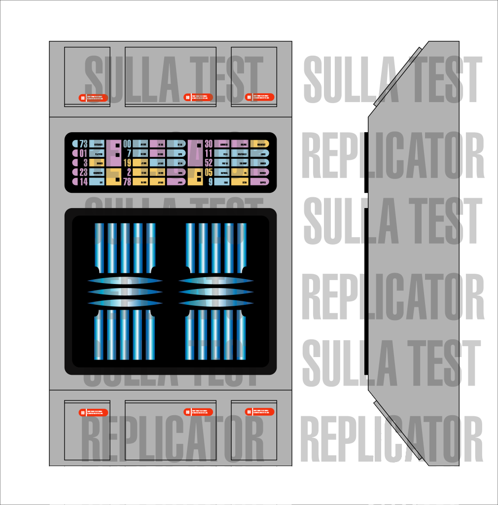
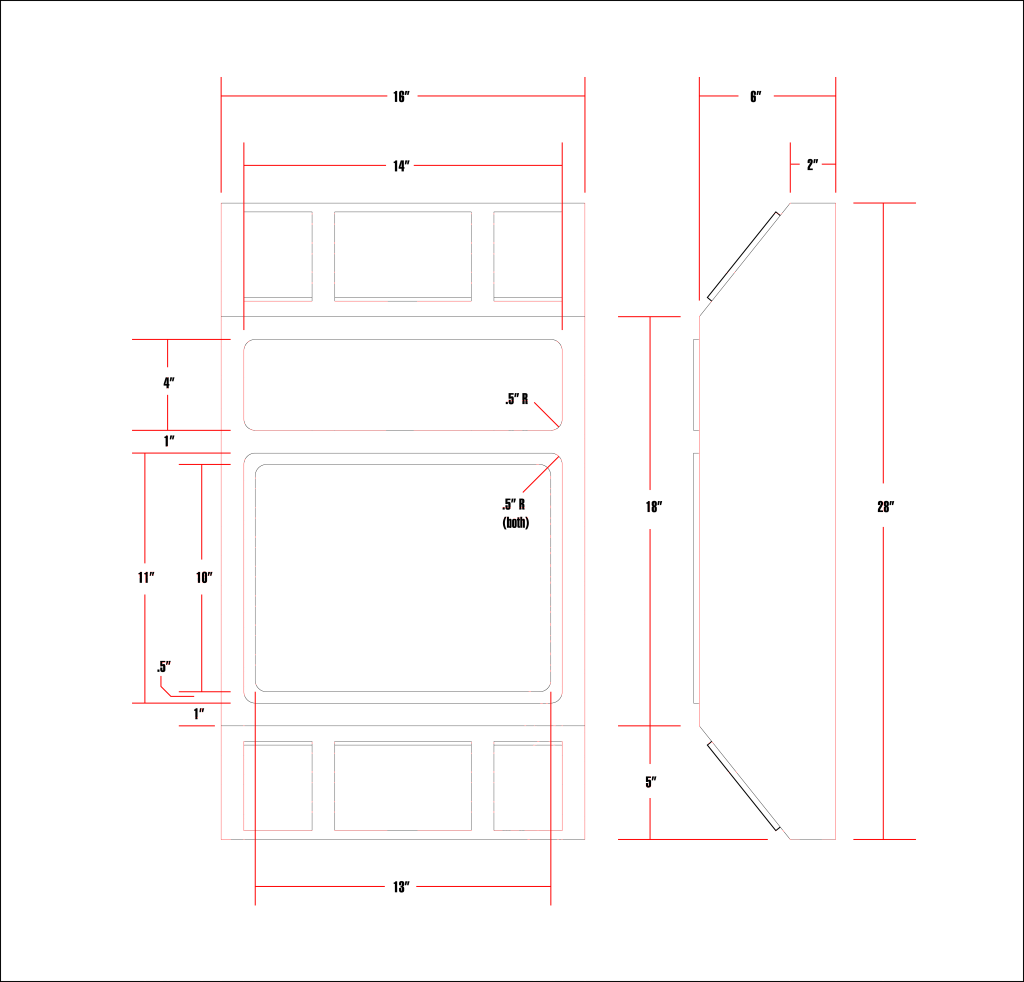
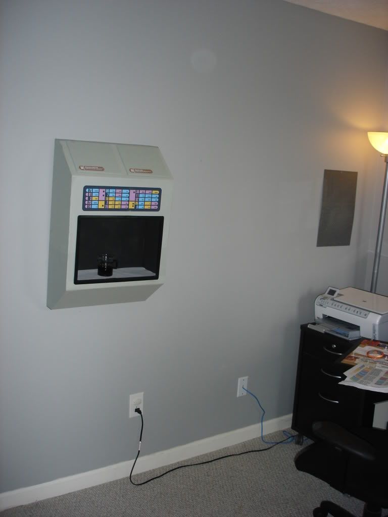
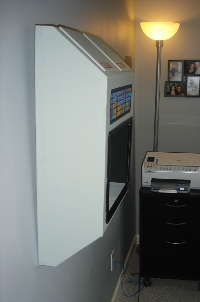
The foam core mock up I made is 2" wider than the drawings, that's why the control panel on top is a little short. The final piece will be made from handy board and plexi with a light shining on the dispenser floor.
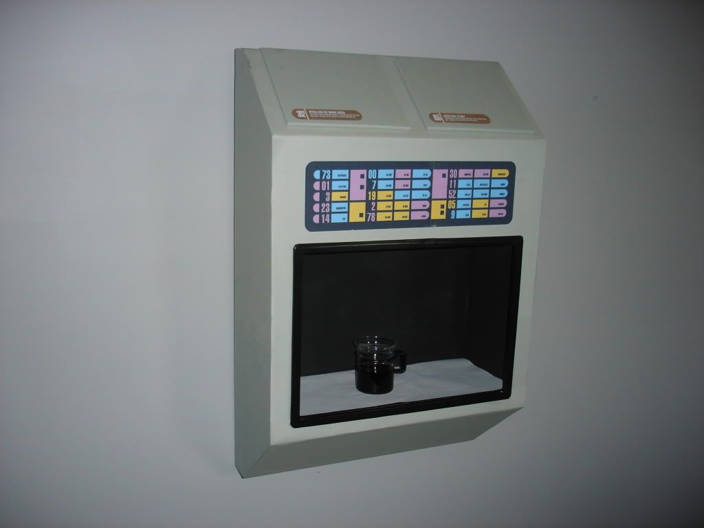
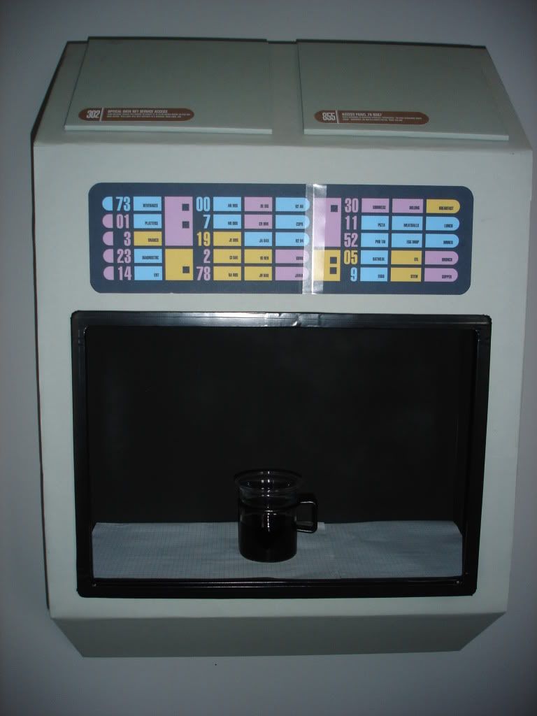
Here's the mock up:
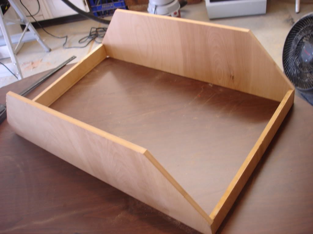
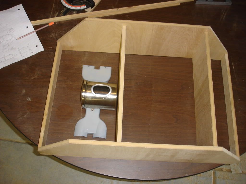
Here's the frame (cut but unassembled).
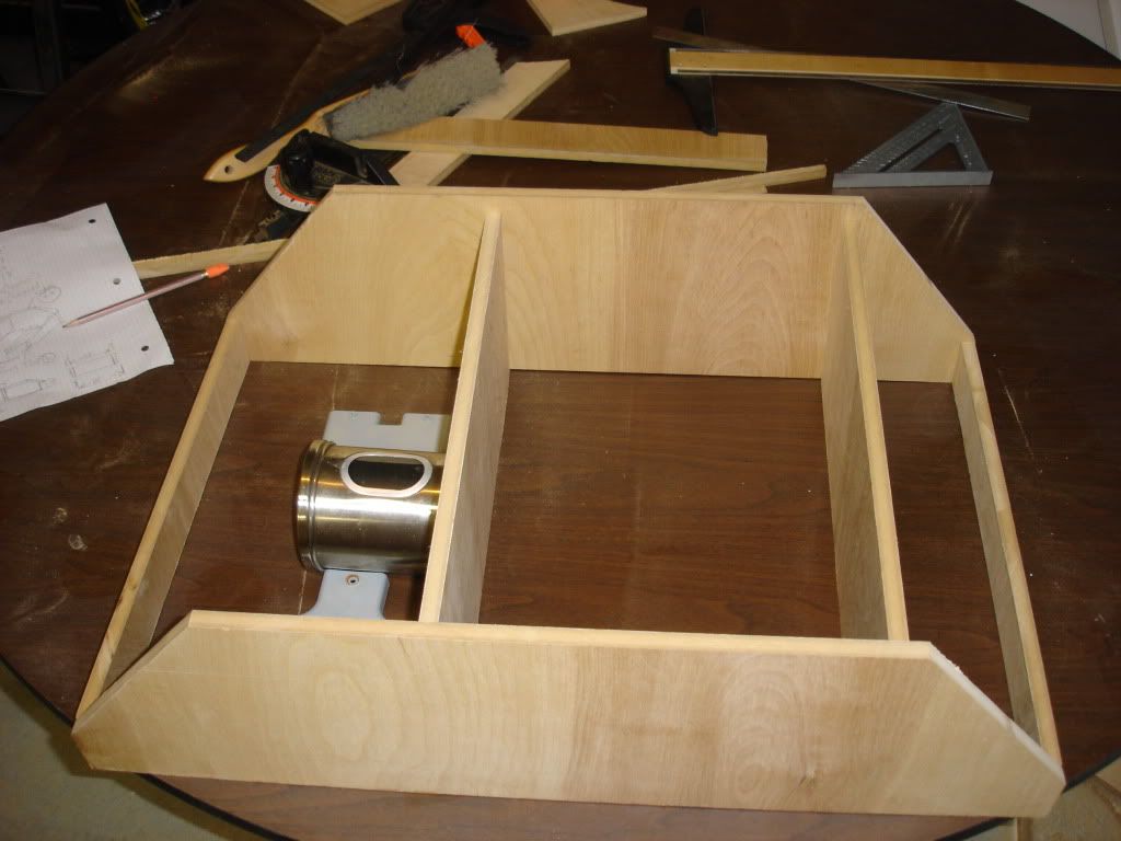
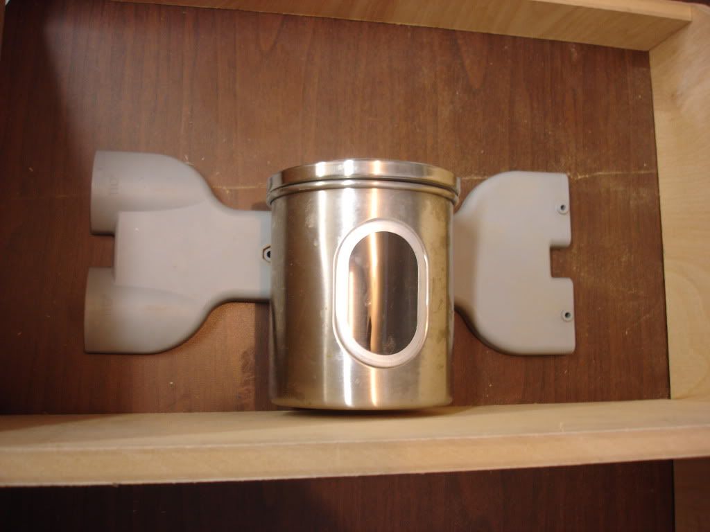
The thingies just laying in there are some bits'n'bots I pulled out of my scrap-crap bin. there's more that will go in there. I plan on using that steel canister with the little window in it as a pattern buffer lit from within. I plan on having some iso chip racks and some ISO circuitry on multi-level plexi in there.
I picked up some lighting for the interior greeblies and for the front dispenser shelf. They will be 120V wall-plug powered with a hidden switch wired in. I'll also most likely be putting some random LEDs in the inside greeblies on a separate circuit powered by 6v lantern batteries mounted in the bottom of the wall replicator.
It will be a little heavy, so two keyhole mounting holes in the back will be needed used with drywall anchored screws for hanging.
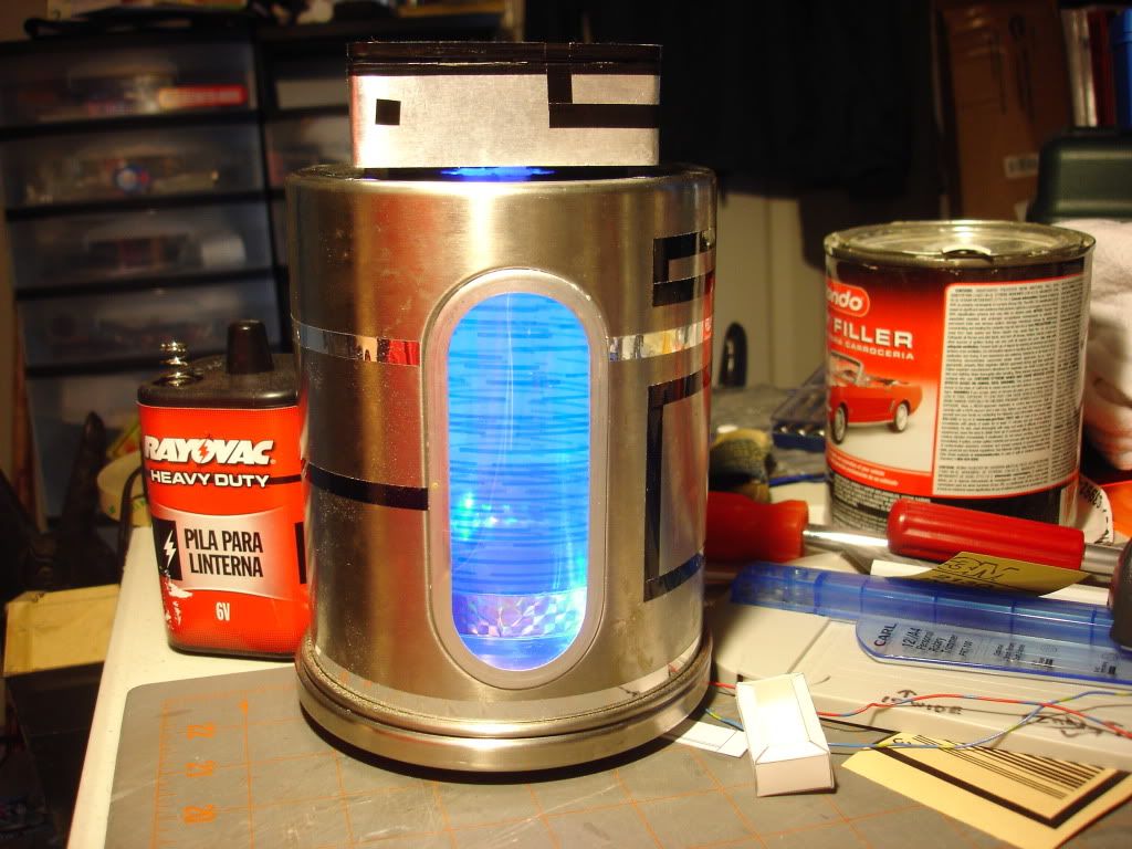
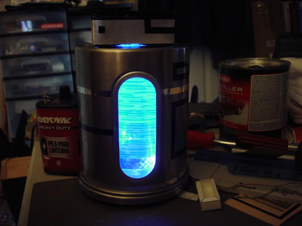
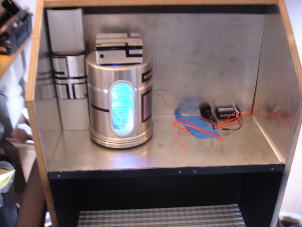
OK, got some work done on the pattern buffer. The wiring is still a bit rough, and the decorative tape needs some tweaking to make it look a bit more professional, but I like it. Here's two pix of it and a link to a short video of it in operation. Excuse the quality, it was taken with my regular digi camera not a video camera.
I'll have pix of the aluminum lined busy box and the new dispenser plate in the actual replicator as soon as the last of the JB Weld sets tonight.
The Video: http://s699.photobucket.com/albums/vv352/boozee2/?action=view¤t=MOV06602.flv
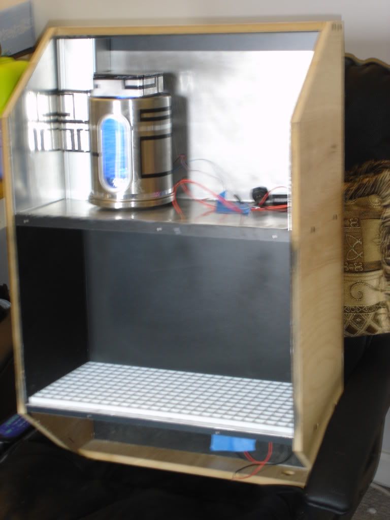
OK, here's some pix of the innards of the replicator so far. I need to polish up the aluminum and work on the greeblies to fill it up. Here you can see a set-in-place test fit of the pattern buffer and it's power source and the dispenser grid plate covering another sheet of aluminum. All the gaps in the aluminum joins are not a problem. They will be covered when all the busy box innards are installed.

The foam core mock up I made is 2" wider than the drawings, that's why the control panel on top is a little short. The final piece will be made from handy board and plexi with a light shining on the dispenser floor.
Here's the mock up:
Here's the frame (cut but unassembled).
The thingies just laying in there are some bits'n'bots I pulled out of my scrap-crap bin. there's more that will go in there. I plan on using that steel canister with the little window in it as a pattern buffer lit from within. I plan on having some iso chip racks and some ISO circuitry on multi-level plexi in there.
I picked up some lighting for the interior greeblies and for the front dispenser shelf. They will be 120V wall-plug powered with a hidden switch wired in. I'll also most likely be putting some random LEDs in the inside greeblies on a separate circuit powered by 6v lantern batteries mounted in the bottom of the wall replicator.
It will be a little heavy, so two keyhole mounting holes in the back will be needed used with drywall anchored screws for hanging.
OK, got some work done on the pattern buffer. The wiring is still a bit rough, and the decorative tape needs some tweaking to make it look a bit more professional, but I like it. Here's two pix of it and a link to a short video of it in operation. Excuse the quality, it was taken with my regular digi camera not a video camera.
I'll have pix of the aluminum lined busy box and the new dispenser plate in the actual replicator as soon as the last of the JB Weld sets tonight.
The Video: http://s699.photobucket.com/albums/vv352/boozee2/?action=view¤t=MOV06602.flv
OK, here's some pix of the innards of the replicator so far. I need to polish up the aluminum and work on the greeblies to fill it up. Here you can see a set-in-place test fit of the pattern buffer and it's power source and the dispenser grid plate covering another sheet of aluminum. All the gaps in the aluminum joins are not a problem. They will be covered when all the busy box innards are installed.
")