lonepigeon said: View Post
I might have the ridge thickness off, but that long highlight is definitely on the ridge and it extends past the base. My drawing is based on the actual photo which is clearer than the Chronicles scan, but some stuff is still lost to the darkness. I only reposted it on top of your scan because I don't have permission to post the original.
Here's a second attempt highlighting some faint, but sharp value differences that might be edges. I'm positive about the outline of the antenna head - that much is very clear in the original pic (yours is too large and drawn too far to the right).
http://www.christrevas.com/rpf/purpleredraw.jpg
Carson's 3D model works well and matches up with pics so I don't see why you can't make it work.
Carson - Is the track scaled correctly in our 3D image?
The base should be about 1/2 inch wide.
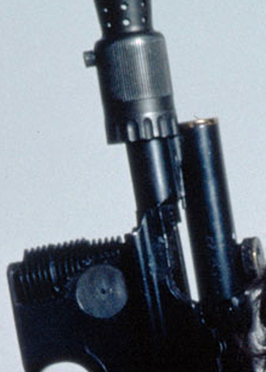
As to why the sight broke the way it did...
T-track is rigid. It was heated and bent into the Sterling holes. Once cooled is holds very tight and you don't even need glue. I'm not sure if it's rigid/brittle enough to break on impact. It may have been cut or broken accidentally in a more direct way like pliers or vise (might explain the two scalloped shaped cuts in the right outlined above). It's easy to see how the antenna fell off since there is very little surface area to adhere to.
PS - T-track matches up in ANH, ESB and ROTJ. There are good ANH E-11 blaster pics that confirm the dimensions.
Any chance since time has passed you have permission to show us the real photo yet?
")
Wow a flurry of activity!
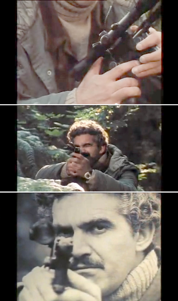
Nice video! Fun stuff.
I would love to see that pic too, but this version of Lonepigeon's purple overlay copies where I originally outlined the antenna head exactly.
The rest of the "base/T Track" outline is just that in my opinion. There is not track base in these images. I believe all those highlights are just glue residue.
I believe I showed fairly conclusively in my comparison images that the side and top highlights and shadows line up and match and it is not possible for the track to be there. If the Antenna/Pushrods were like the MR design, the Antenna would sit too high and the edge of the track would be very evident, but can not be seen in any photos. I think it is like the MerrSonn with the antenna sitting on the barrel next to the upright blade of the track.
Either the base was ground down to next to nothing (very thin) OR the sides were ground off.
Now that we know what the actual size and shape of the antenna thanks to Carsons great find, we can tell exactly where that one (right side) antenna is placed. Carson did a great job estimating the dimensions as well. VERY close to the molded parts!
The HERO screen used and post production images only have the one right side antenna (and part of the pin in some shots) the rest is glue reside in my opinion.
My thought is that when they first made the prop, it had the two antenna heads with a blade between. Maybe the track was cut like a ramp sight ( which would make sense for an armorer to do making it look like a front sight) or it was left square like the MerrSonn, but since no photos or screen shots show any evidence of either of these, it is up in the air...still. But there is no way IMO that the antenna could be sitting on the track base, it is simply too thick and would make the "sight" sit too high above the FH. Just look at some of the examples and compare.,,but remember that the publicity image of HF shows the FH tipped up! (the back edge of the FH is sitting on the top of the bull barrel) which makes the antenna "seem" to sit higher in that photo! Take out the booster and fit the FH and tip it against the top of the barrel yourself. You will see how much higher the antenna sits then and see that it does not make sense.
I personally intend to do the ramp blade and antenna on barrel type. I will compare them to the publicity photos when finished. Maybe that will help get closer to an answer.