Iron man motorised faceplate electronics tutorial!!!

to be clear.. you should only have 1.. (or ensure you have the LOWEST resistance on the path you want the circuit to take)

either pull UP or pull down.. to make the pin non-floating as mentioned..

for myself.. I have a habit ofa lways using the INTERNAL pull-up resistors.. its less physical parts on a board/project..etc..
 
You have to make your own, dude, every helmet is different, they don't have the same interior surface or the same size, so there isn't a universal template, look on the other iron man threads and look for the basic design and make your own to work with your helmet.
 
Resistors goes both ways, they are not like diodes.

the resistor is used to pull the pin down, micro controllers don't like to have any active pin floating, so you have to attach it to ground or to VCC

the Arduino already have internal resistors that you can activate via code, but just to be cautious it is good to use another pull down

to be clear.. you should only have 1.. (or ensure you have the LOWEST resistance on the path you want the circuit to take)

either pull UP or pull down.. to make the pin non-floating as mentioned..

for myself.. I have a habit ofa lways using the INTERNAL pull-up resistors.. its less physical parts on a board/project..etc..

If I understand what you guys are saying is that pin 2 is always receiving power and thus is floating. The board doesn't like this so you ground it out with a resistor inline to where your ground is located. Thus you are pulling down since voltage would be near zero?

Pull up you are upping the voltage

Pull down pulling voltage down by using resistance?
 
Djstorm100 -

here a link from wikipedia with some info

Pull-up resistor - Wikipedia, the free encyclopedia

But basically, what a Pull-Up resistor does is to keep the logic HIGH (1) on the pin, pulling the current from it in a weak way all the time, so anything that pulls it to 0V will make the logic LOW, like when you press a button connected to the GND.

and a Pull-Down does the same on the opposite way, keeping the logic level of the pin aways LOW (0), and anything that drag it to 5V will make the logic HIGH.
 
what memebr said..


the reason is so that there is a DEFINITE state of the pin.. doesnt matter what it is.. but its STABLE.. but 'floating' meaing the pin is not tied to ANYTHING.. and hence interference (air, other components..etc) can add NOISE to the pin.. and make your code faulty/not reliable..


if the pin is floating it can be bouncing around between 0 (low and 1 (high).. or in between..etc... when you are expecting your code to check for a 0 or 1..your code could not provide the correct feedback/results..or even trigger false positives..etc (ie; like a button was pressed but it wasnt)

it was hard concept for me to grasp.. but after a reading/links.. and playing around.. you'll get it..

I think in starting to understand it. Since the pin is floating due to the switch being open the current cant go anywhere and thus may cause noise. So to fix this you add a resistor to complete the cuircut but only allowing very small amount of current, this makes the code/pin/board happy. When the switch is pressed the jump in current tell the board that the pin has been trigger.


I hope that's right lmao!
 
Actually the pin floats when it is activated but without any "use", the pin need to be in "use" 100% of the time, so it can not be accidentally trigged by any noise in the circuit or any other thing, like your hand...

A typical pull-up resistor application:
The resistor is connected between the power supply and a pin, a switch is then connected between the pin and ground, when the switch is open, there is almost zero current that flows from VCC through the resistor and into the pin, the voltage at the pin is given by the following equation from Ohm's law: V=I.R

Since there is no current through the resistor, there is no voltage drop across the resistor, making the voltage at the input equal to VCC which causes the input to read "high", when the switch is closed, the pin is connected directly to ground driving it "low", as a side effect of closing the switch, current flows through the resistor according to the following equation (also from Ohm's law):
Ipullup = VCC - 0V / Rpullup

In some systems, "Ipullup" is a significant amount of current through the pull-up or pull-down resistor, Increasing the value of the resistor can reduce this current while simultaneously causing the pull-up or pull-down to be "weaker" (adding another resistor in series with the pin), a weak pull-up/pull-down resistor typically has a value of tens or hundreds of kilo-ohms while a strong pulling resistors have values of a few kilo-ohms and can override a weak pulling resistors if both are used on the same microcontroller pin (a resistor in series with the pin while the weaker built-in one is deactivated)

Pull-up/pull-down resistors are a great way to prevent microcontroller inputs from assuming undefined values, however, they must be correctly sized (either weak or strong) based on power consumption requirements as well as existing circuitry (such as internal pull-up/pull-down resistors) to ensure proper circuit functionality.

That was a Pull-up example, but the Pull-down is the same thing in a opposite way.

Also, there is a bunch of nice material over the internet on the subject, including youtube.

Thanks member, I was searching on the net but wasn't still grasping the concept.

The arduion board is just for testing purpose? Curious if there was a smaller board that could do the same thing.

How would you make the connections to the board more soild?
 
IMHO.. some Arduino boards are just for DEV/testing purposes..

because of cost or size (or both)... they come with stackable headers for easy & quick connections for testing/prototyping..

makes it a bit more difficult to make permanent connections unless you use the bottom of the board,..try to remove the female headers...etc..

some of these variants also have extra stuff you really dont 'need' in the en project (barrel jack, usb port perhaps....etc)

as of late..Arduinos have really come down in prices and increased in availability....
and some of the smaller boards (nano, pro/pro-mini, micro)..etc..etc..

are void of some of these extras..very small footprints, no headers...where you can solder directly to the through hole of the desired pin.. (and cheap!)
these are mostly the ones "I" would consider as 'leave-in' boards for your end prop/project.. :)

ultimately, you can build a nice, stable Arduino for around $5-$7.00 or so,,, and even buy 'kits' for around $9.00... but then your close to just getting a nano/pro-mini for the same price.. and no work.. :)

but you wait for shipping to come..
 
just completing what xl97 said:

I personally like the Pro-Mini board that sparkfun sells ($9.60), like he said those boards were created as "leave-in" boards, to use on the final assembly.

If you use a Pro-Mini, make sure to buy a FDTI adapter with it, so you can upload your programs to the board.
 
this is one I use:

CP2102 USB 2 0 to UART TTL 6pin Module Serial Converter | eBay

(I think you can even find them cheaper.....shipping isnt so quick!) ;)

they have worked flawlessly for me.. on every custom board I have ever made..

you can do a quick mod to breakout the RESET/DTR pin for it..

and it has BOTH +5v and +3.3v outputs!

I know some of the boards dont come with voltage regulators or something.. so just be diligent in your reading and set-up..
 
DEV-11113
Arduino Pro Mini 328 - 5V/16MHz

DEV-09717
FTDI Cable 5V VCC-3.3V I/O

6 Pin Right Angle Male SMD Header

This is all I would need... the FTDI cable they have 5 volt and then 5v-3.3v (which is the one I picked, the last one)


Just comfirm pro mini has digital pin outs (14 to be exact) If you are using a voltage higher than 3.3 or 5 (depend on board) use the RAW pin NOT the VCC.
 
Last edited:
Djstorm100

The correct cable for you would be the 1st one, 5V straight (DEV-09718)

about the RAW, this is the VCC feed pin with a not regulated power supply, such as a 9V battery.

LOL, 17 bucks for a FTDI adapter is a lil too much bro, you can buy this one xl97 posted, it is a good one, you can look fot those with the FT232RL chip also.

it is still expensive, but if you wanna lay your hands on it fast:

FTDI Friend + extras [v1.0] ID: 284 - $14.75 : Adafruit Industries, Unique & fun DIY electronics and kits


xl97
nice ebay store! i just bought some things with this seller, thanks for the tip!
 
Last edited by a moderator:
no problem..

I too said its a bit pricey... (could get two more mini's!) :)

but the shipping wait from China can be a 'killer' for motivation too! lol.

the good thing is, once you have a nice foundation of tools (programmers, Arduino boards)..

future projects wont cost as much..

I've said it before.. and I'll say it again..

I recommend EVERYONE get an Arduino Duemilanove or Uno (not SMD chip version)..... EVEN IF THEY PLAN ON USING A NANO OR PRO-MINI in their end projects!

They are great for testing components with breadboard set-ups to ensure your logic/ideas are sound.. practice with components that are new to you..
and you can use your Duemilanove/Uno as a programmer to FLASH bootloaders or upload sketches to your custom boards or blank chips if you want.

Matter of fact that has been the ONLY way I have ever flashed a bootloader onto my chips..

Arduino board ad Arduino IDE as ISP..


ICSP = used to flash bootder
FTDI = used to upload sketches..

more boards (even blank chips now a days) come with the bootloader already flased on the chip.. so most people dont worry about that.. (mostly for new or blank chips or more advanced people use diff bootloaders for different things)


Just recently.. I have been BY-PASSING the bootloader all together and using an ICSP cable to upload my sketches.. (makes very fast boot times and more space left on chip)..
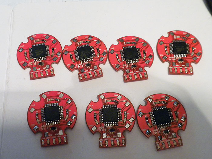
to be clear this are on PURPOSE built boards, not really an Arduino..

example:

batch1_completed-003_sized.jpg


these are 'Arduinos'... for lack of a better term..
they are the same minimal Arduino circuit design...

but instead of breaking out all I/O pins.. I only broke out the pins that are used for this project (just some leds and some audio)..

I flashed these with Arduino bootloader like I would any new/blank chip.....
and used the FTDI cable (linked to above) to upload my code/sketches..

done deal...

however.. learning more and getting a new/special ICSP cable..

I learned I can not use a bootloader and upload directly to the chip... (kinda making it NOT an Arduino anymore as there is no bootloader and the IDE can no longer be used to upload sketches)


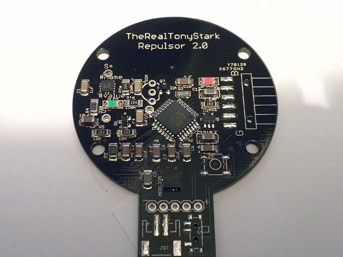
looking at this project for example:
IM_repulsor_v2.0-buildPics-005_sized.jpg


it had some obstacles to overcome..

initially there was no ICSP header on the board? ow are we going to get a bootloader on there then! (yikes!)

well purchased a cable from Hobby King that does ICSP on the SMD chip directly.. (meaning there doesnt need to be a header or pads broken out.. which helps when you have to overcome 'mistakes' like this!)

if you look at the irght side of the pcb..you'll see the (missing) header section..

this is the FTDI headers.. where I would normally just hook up the FTDI cable and upload new sketches..

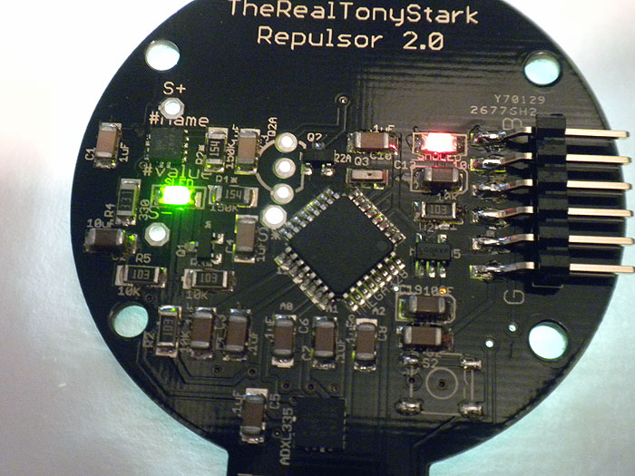
better pic with header installed:
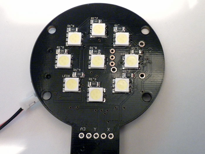
IM_repulsor_v2.0-buildPics-008_sized.jpg


led side:
IM_repulsor_v2.0-buildPics-011_sized.jpg


this is using more or less the same principle as we outlined here..

a bunch of leds... triggered/toggled by a transistor..

this just happens to be a custom board with all that junk built in.. instead of piecing it together with an Arduino..
 
Thanks for all the help...yes the cable is crazy ***** pricy but I need it for this weekend when I lock my self in my workshop to get ***** done! lol

Xl I really really like that replustor... I need 2 please :)
 
HAHA..

those arent mine.. did those for member TheRealStark here..

but they are getting a re-deisgn one way or another...

so stay tuned. :)


(getting some extra I/O's.. and possibly BlueTooth so you can remotely trigger/control your gloves (like Extremis armor) ;)


good luck@!
 
xl97

so you are burning on the chip directly via SPI bus, burning the HEX file directly to the chip itself without any bootloader?


edit:

This thread is getting pretty serious now :ninja
 
Last edited by a moderator:
@xl97

so you are burning on the chip directly via SPI bus, burning the HEX file directly to the chip itself without any bootloader?


edit:

This thread is getting pretty serious now :ninja


yep..

well I believe that is what its doing.. but its alot simpler in practice.

open Arduino IDE
upload code/sketch using programmer
I use this cable (love it so far) Atmel Atmega Socket Firmware Flashing Tool


but again.. thats because these boards are PURPOSE MADE.. an END PRODUCT... meaning these are NOT meant to have different code uploaded to them over and over and test things with (that is what the Arduino UNO or Duemilanove boards are for).. this is when you have your final circuit worked out and code/firmware done..etc..

the spider-man web shooter pcb's (red ones).. I am choosing to do it this way to keep the boards cleaner and makes it faster for me. (although I had originally designed it to be the 'regular' way, 2-part flash bootloader then upload code using other wires..etc)

the Repulsor pcb, that was done out of necessity...lol.. (either the chips had to be ordered WITH the bootloader on it already from digikey or wherever... or we had to use that cable to FLASH the bootloader the chip...and/or also use it to directly upload the sketch as well if no bootloader is needed)

for myself in this instance.. it saves me the time of having to SOLDER on wires to the ICSP bus.. and then again to RX/TX/DTR/V+/GND (serial) to upload code..

there is no benefit from having the bootloader on these PCB's really.. :)
 
Last edited by a moderator:
I may do it for my helmet circuit

Using a Mega328, with the HEX direct on it, and a minimal aproach on the PCB, with just what i need.
 
This thread is more than 4 years old.

Your message may be considered spam for the following reasons:

  1. This thread hasn't been active in some time. A new post in this thread might not contribute constructively to this discussion after so long.
If you wish to reply despite these issues, check the box below before replying.
Be aware that malicious compliance may result in more severe penalties.
Back
Top