Phase II Enterprise Study Model

I started the impulse engines yesterday, and started filling and shaping them today...

p2_1701_015.jpg

I also cut out a lower sensor dome. I'll be shortening it and making a base for it, but even in it's current state it seems to fit pretty nicely...

p2_1701_016.jpg

I've also been doing some more sanding of the primary hull and should get around to hitting it with another coat of primer tomorrow night. I'm hoping to have the secondary hull interior finished enough to close it up by Saturday so I can finally get the hangar elements assembled. After that, filling and sanding of the secondary hull can start up.
 
Very nice progress I must say. The neck pylon seems a little tall, but I think this is probably an optical illusion since it doesn't have the front phaser bank extension added to it yet.
 
It will sit slightly lower once I finish the secondary hull modifications. Because I couldn't be absolutely sure how the top curvature of the secondary hull was going to be effected by closing up the hole for the original dorsal, I cut the bottom edges of the replacement dorsal straight across. The spine is the correct length, and I believe the leading edge as well, but between them needs to have a small amount of material removed... I just don't know exactly where yet (but I'll most likely have that aspect fixed by Monday).

The height of the dorsal is actually the same as the kit part it is replacing. The plans I made above I printed out, covered with clear packing tape (front and back), and then cut out as templates for cutting the styrene parts it is made out of. I'll be doing the same process with the nacelle support pylons (which have a similar wing shape to them).

The wing like cross sections of the three pylons is an interesting touch by Jefferies. Unfortunately it doesn't look like it was done on the studio model's nacelle support pylons, and was dropped completely from the TMP design. There are some really interesting geometric aspects of this design that I don't think have been fully fleshed out before... and I just hope I'm able to do them justice in this build.
 
Well, Jefferies being a designer did like to put some interesting shapes into his stuff. But I imagine the model builders opted to simplify the designs in spots. The engine pylons are one area I can see that happening as the things have to go up at an angle, and yet they also sweep back. Throwing in a tapered triangular cross section (although trapezoidal might be a more apt term to match the side profile of the saucer) can make things even a bit trickier for parts fabrication and trying to get all the angles to line up properly.

If you look, even the warp engine side profile mirrors the saucer a little as well with its trapezoidal profile (something that carried over into the TMP refit).

At least Jefferies liked going for simple shapes. Probert and other designers after him went for long sweepy complex curve shapes to give the model a more art deco design. It is almost like a starship design comparison of Syd Mead to Moebius (angular and flat in several creations compared to curvatious) in their approaches. Or one might call it "old school" versus "new school".
 
Put some more time in on it this weekend... mostly on the interior of the secondary hull. I should be closing it up soon and then starting in on the hangar area (most of the parts I need for this are ready to go).

Reassembled the model to see how my progress was looking...

p2_1701_017.jpg
 
I finally got everything I needed to get done on the inside of the secondary hull in place and closed it up. I then attached all the hangar/fantail elements.

p2_1701_018.jpg

From there I started to resculpt the secondary hull surface. I'm pretty happy with where I've gotten to with the shape of the secondary hull... but I think I could have done it better (or at least easier) if I had just scratch built the whole model (which is what I'll be doing on my next project).

I've put some more time in on both the primary and secondary hulls over the last few days. On the primary hull I've mainly been working on sharpening up the upper edge. With the secondary hull, I'm in the beginning stages of removing the last of the smaller surface details from the kit parts, erasing the edges where the new parts were added and resculpting the fantail/undercut.

p2_1701_019.jpg

Since that involved a lot of puttying and waiting, most of the time that I've dedicated to this model during all that has been in cutting out the pieces for the nacelle support pylons and working out how they'll go together. Because the openings for the grills are close to the back edge of the supports, I when out and bought some thin styrene for backing them. I also bought the corrugated styrene I'll be using for the grill work on the supports and forward grills on the nacelles. The center indentations on the nacelles will most likely be done using individual strips of styrene to make that grill pattern.

Right now the supports are a collection of pieces of styrene, but hopefully by Monday or Tuesday I'll have something worth photographing for you guys.
 
Lookin' awesome there, Shaw! :) I've yet to actually get my three-foot Phase II Enterprise started (had some issues with the base assembly of the saucer, so put it down and haven't gone back to it since).

I'm glad you did up those cleaned up schematics of Matt Jefferies' original design, as I don't think I'd have even been able to consider building my own without them. So again, many thanks for that.

Now, I know you're more of an expert on this rendition of the Enterprise than I am, but regarding your reference to the size of the uncompleted filming model, I thought it was eight feet long? Like the TMP model?

Definitely lookin forward to seeing more of this build. I love this ship!
 
Thanks!

Yeah, the filming model was only about 5' 4" long (and a little more than 30" wide). The model was built at the same scale as the larger Jefferies' plans (which were originally on a 24" x 36" sheet). Jefferies packed a ton of information into a single sheet by having the front half of the primary hull drawn over the back half (which also gives you the elements needed for the front view of the primary hull).

The excuse that Paramount gave for starting over with a new model was that the Phase II Enterprise was too small for the big screen. This, obviously, wasn't true because the Reliant was the small approximate scale and looked just fine. The real reason seems to have been wanting to give Magicam (owned by Paramount) the chance to get a big budget model credit under their belts.

The best way to see the size difference between the TMP Enterprise model and the Phase II Enterprise model is by looking at one of the Planet Hollywood models in it's new home inside the TMP Space Dock (here).


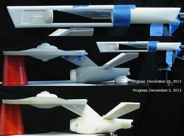
Quick progress report...

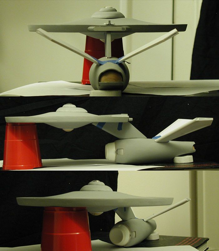
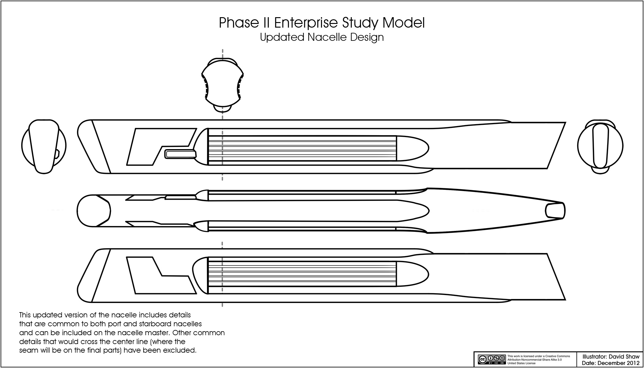
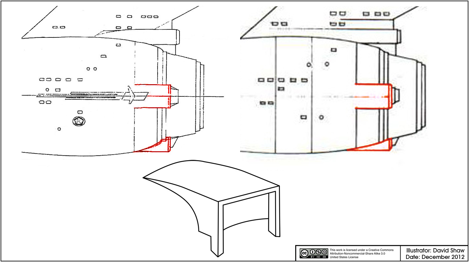
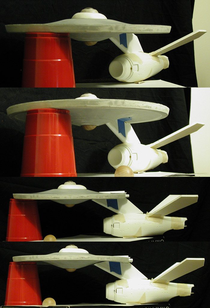
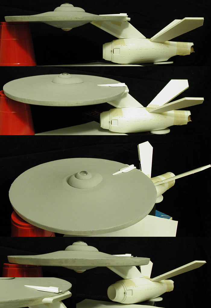
So this is a good example of why I'm building a study model before attempting a full set of plans of the Phase II Enterprise. Similar to how the Price/Loos model didn't follow Jefferies' plans on the dorsal pylon, the model doesn't seem to have followed the plans for the nacelle support pylons either. Oddly enough, the model's supports are more like the TMP studio model's in overall geometry.

I'll draw up some comparison diagrams of what Jefferies' had designed with what Price/Loos built (including some photos) when I get the chance. But what started out as a project to do one set of plans is definitely going to end up as two distinct sets of plans of the Phase II Enterprise.

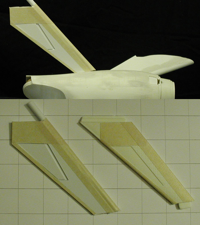
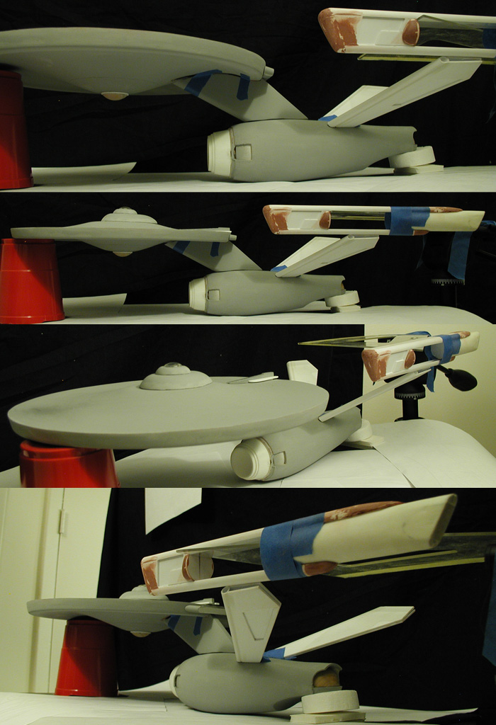
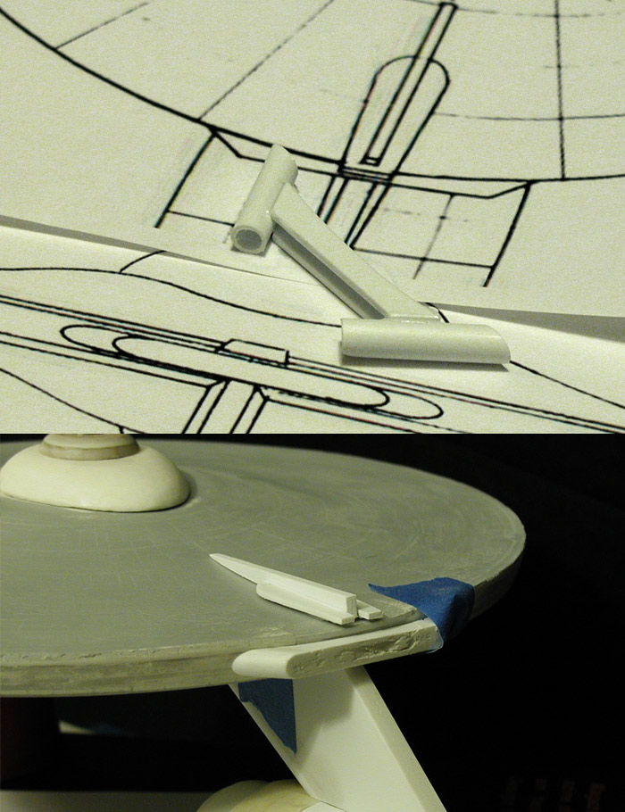
I taped together the parts for one of the supports (with a quickly cut stand-in grill, the final grills most likely won't be made until I'm ready to paint the model) to see how they worked. I've ended up with the shapes I was going for, so I'm pretty confident that I'm on the right track with these. I won't finalize the top or bottom edges until after I have the primary hull, dorsal and secondary hull together as a single piece (so I can make adjustments in the overall alignment of the model).

Here is how the taped together support looks (and a comparison with the original kit's support)...


p2_1701_020.jpg

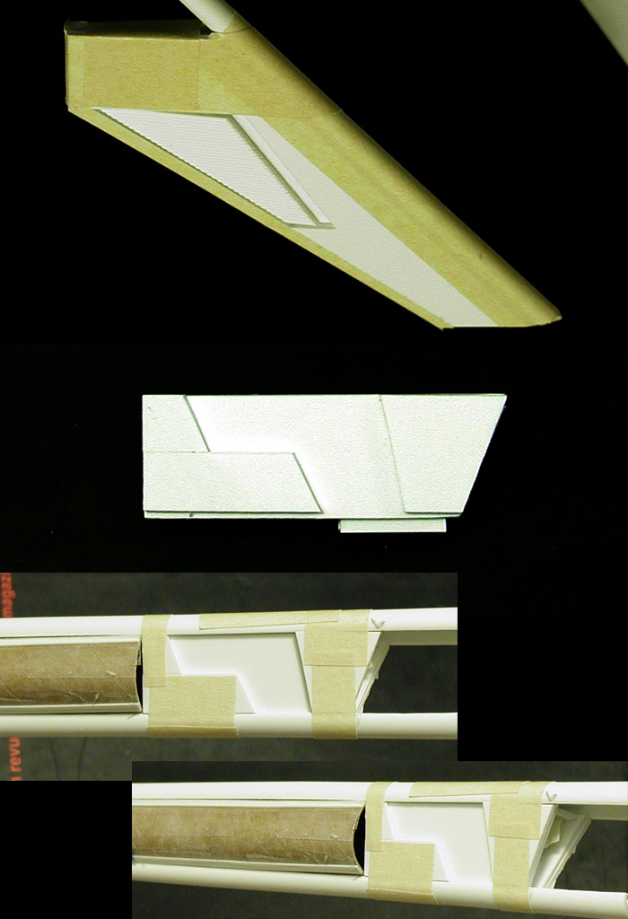
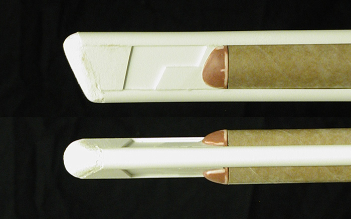
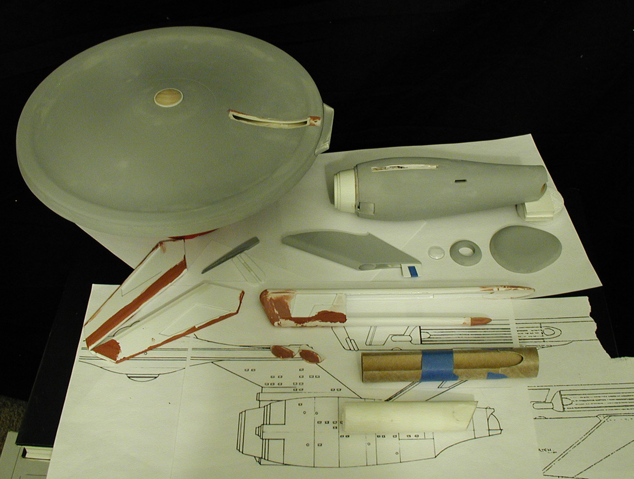
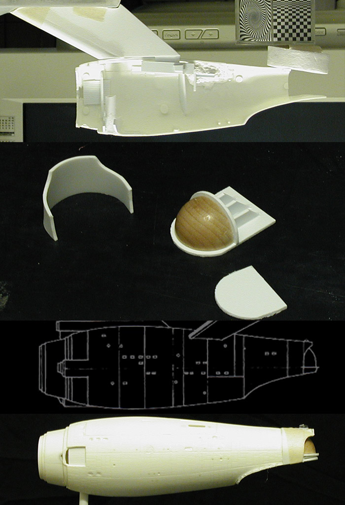
I spent most of this week working on the front half of the nacelle master. I cut out the many pieces that make up the front third and glued them together. I then cut some styrene tubing in half to make the lengthwise contours of the top and bottom of the nacelle. Before I cut those to their final length I tested their fit with the front third section and a stand-in section of cardboard tubing (covered in packing tape so I can sculpt the ends of the top and bottom sections later on without them sticking to the tubing) to make sure everything was coming together correctly.

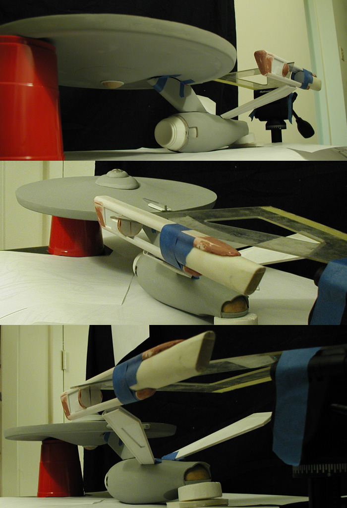
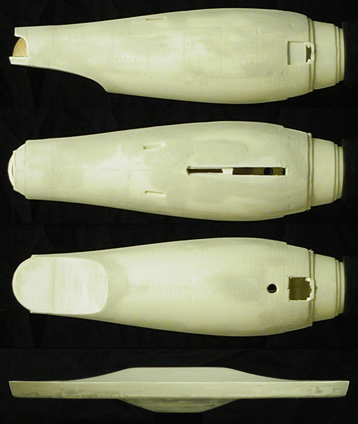
Below is another shot of the test assembled nacelle pylon support (this time shown at the approximate angle you'd see it at from the side), the front third section of the nacelle by itself and a couple shots of the test assembly of the front half of the nacelle master.

p2_1701_021.jpg

I still need to get to the center section with the grill work. Once that is done, I need to graft it to the rear section of the nacelle I made earlier to complete the back half of the nacelle master. It is slow going, but I think what I'll end up with is a really nice looking nacelle which (hopefully) will yield two nice nacelles for the model.
 
Started assembling the nacelle support pylons yesterday, and I did a test assembly to make sure that they are going to reach the (approximate) height that I'll need for everything to align correctly. This is most of the pieces just set together, so some things aren't in their exact positions... but it does let me know where the supports are relative to the primary hull.

p2_1701_022.jpg

And that is pretty much where I was hoping they would be.
 
I'd be posting more in this thread with all the eye candy. But there are only so many times one can post "Wonderful, amazing, etc..." before starting to sound like a broken record. I'm really liking the work on this and you've certainly given me some ideas to do on my model.

What's your source for these wooden domes you're using for the sensor, bridge and hangar bay doors?
 
Thanks Guys!

It is always nice to know that people are still following along.


What's your source for these wooden domes you're using for the sensor, bridge and hangar bay doors?
At a couple of the hobby/crafts stores I go to they sell small wooden spheres in bags of four or six (or more if they are smaller). I had bought solid spheres back in 2008 when I was considering using them as nacelle domes for my two-third scale 33 inch replica (I was playing with the idea of doing the pilot version at the time). In the end I used one for the hangar doors on my second attempt... and as it turned out I still had the leftover pieces of that sphere, so part of those are now the hangar doors on this Enterprise (which makes sense as the two models are the same scale).

About a year ago I bought some with openings drilled out of the backs (to be used for a life-like baby seal project I've been working on). I had more than I needed (I only needed two... maybe three if I messed up), so I cut off the end with the hole to build the bridge and the other end to make the lower sensor dome.

They were a pain to cut (all I have is an Xacto hobby saw), but the results were worth it.


I've made some more progress on the nacelles... mostly gluing the larger pieces together and then trimming them down to where I needed them. Here is a shot of the nacelle with the rear quarter taped into place (but without any center section), as it should be aligned with the rest of the model when finished (I bumped the model since the last shots, so the overall alignment got messed up a little), and a comparison progress shot from about 3 weeks ago.

p2_1701_024.jpg

It all seems to be coming together as planned... no major surprises or anything so far. Of course I still need to make molds of the bridge/B/C deck and nacelle master, which should be interesting.
 
Made a little more progress since yesterday, mainly sculpting some of the areas of the front sections of the nacelle.

p2_1701_025.jpg

Hopefully I'll have the nacelle done within the next week or two, which means I need to go back to the bridge/B/C deck part and finish it up (as these are the two areas I'll be making molds of when their done).

I still need to get the bridge to the shape I want, add the turbo lifts and then attach them to the B/C deck. I'll most likely not spend any more time on the bottom edge of the B/C deck because that area will need to be cleaned/shaped on the final part to smoothly match the primary hull's curves.

I've been slowly plugging away at the primary hull, and I'm pretty close to where I wanted it. Once I reach that point I'll attach the dorsal. The secondary hull is coming along nicely, but I still need to cut off the front ring (which isn't circular) and replace it (that part was actually made a few weeks ago). Once I'm happy with the secondary hull's surface, I'll attach it to the primary hull and dorsal. And with those three pieces together I should be able to make any final modification/adjustments to the nacelle support pylons.

So that is the overall plan going forward.

Now that I'm starting to get close to finishing the nacelle master, I've had to start deciding which details to include. I've ruled out any details that cross the center line because there will be a seam there I'll have to deal with. But one element, a small rectangular piece on the front section of the nacelle has been giving me trouble ever since I first started studying the Phase II Enterprise. It seemed like it was only on one side of the nacelle, and at first I figured that what ever side I picked (inboard or outboard) it would be reflected on the opposite nacelle. After studying every drawing I have of Jefferies and every reference photo I have of the Price/Loos models I've reached the conclusion that it is on the left (port) side of both nacelles (both port and starboard).

So I'll be adding it to the master...


It is a very interesting element for Jefferies to use to break the symmetry of the design with. And for the longest time I was sure I was missing something that would show that it should be on either the inboard or outboard, or both. This definitely wasn't the conclusion I had expected to reach.

The next element I plan on starting in on will be the sensor platforms around the deflector assembly. While I'd like to have all the same detailing that was supposed to be there on the studio model, I may need to simplify the design a little for the scale I'm working at (approximately one-third scale to the studio model). This is what I plan on building...


It should be interesting... specially since I need to make the part three times.
 
Wow amazing documentation and knowledge of the Phase II design being shared here. A subject I had always wanted to learn more about.

Thanks and keep up the great work. Really enjoying the attention to detail and consideration every step of the way.
 
Thanks!


So after making a little more progress today I decided to take some more test assembly shots (I can't help it, I'm curious as to how the model will eventually turn out)...

p2_1701_027.jpg


p2_1701_028.jpg
 
Quick update...

I made progress on the middle third of the nacelle today. If everything continues to work out nicely, I'll join it to the rear section I made towards the end of November. I've got some more puttying and sanding to do on the newer parts, then I'll give them all a primer pass to see where they stand before Monday.

I figured I'd show something a little different today... the Enterprise as she actually is right now, a collection of parts.


So yeah, right now there is very little that is whole. All of the parts are being worked on until I'm happy with them, and the first two major parts to come together will be the primary hull and dorsal. The dorsal is in good shape, but I still have some things I want to address on the primary hull.
 
I'm debating making the bridge/B/C deck and nacelles available (as those are parts that will be molded to make the final parts for the model).

Considering all the work I've done to the primary and secondary hulls, I've thought about making molds of them too (as there is very little of the original kit aspects left). The thing is, if I was going to do that, I should have just made them from scratch as well (to make them as accurate as possible).

I thought about (once I've nailed down the plans) doing a half studio scale version from scratch... but that would make it almost the same size as the 1/350 refit. I think that is just a little too close to the size of existing (commercial) kits to justify that amount of work.

So the long and short of it... I don't know yet, but I'm weighing the options. :unsure
 
Well let's see... there are already 350th kits of the TOS and Refit ships... Perhaps some sort of conversion kit... :D

k
 
This thread is more than 8 years old.

Your message may be considered spam for the following reasons:

  1. This thread hasn't been active in some time. A new post in this thread might not contribute constructively to this discussion after so long.
If you wish to reply despite these issues, check the box below before replying.
Be aware that malicious compliance may result in more severe penalties.
Back
Top